-
1 падение или повышение напряжения при заданном режиме нагрузки
падение или повышение напряжения при заданном режиме нагрузки
Разность между напряжением холостого хода обмотки и напряжением на ее выводах при заданных нагрузке и коэффициенте мощности при условии, что к другой (или к одной из других) обмотке(ок) подведено напряжение, равное:
- номинальному, если трансформатор включен на основное ответвление (в этом случае напряжение холостого хода рассматриваемой обмотки равно номинальному);
- напряжению другого ответвления, на которое включен трансформатор. Падение или повышение напряжения обычно выражают в процентах напряжения холостого хода рассматриваемой обмотки.
Примечание — В многообмоточном трансформаторе падение или повышение напряжения зависит от нагрузки и коэффициента мощности не только данной обмотки, но и других обмоток
(МЭС 421-07-03).
[ ГОСТ 30830-2002]EN
voltage drop or rise for a specified load condition
voltage regulation for a specified load condition
the arithmetic difference between the no-load voltage of a winding and the voltage developed at the terminals of the same winding at a specified load and power factor, the voltage supplied to (one of) the other winding(s) being equal to:
- its rated value if the transformer is connected on the principal tapping (the no-load voltage of the former winding is then equal to its rated value);
- the tapping voltage if the transformer is connected on another tapping.
This difference is generally expressed as a percentage of the no-load voltage of the former winding
NOTE – For multi-winding transformers, the voltage drop or rise depends not only on the load and power factor of the winding itself, but also on the load and power factor of the other windings
[IEV number 421-07-03]FR
hute ou augmentation de tension pour une condition de charge spécifiée
différence arithmétique entre la tension à vide d'un enroulement et la tension en charge aux bornes du même enroulement pour un courant de charge et un facteur de puissance spécifiés, la tension appliquée à l'autre (ou à l'un des autres) enroulement(s) étant égale:
- à sa valeur assignée, si le transformateur est connecté sur la prise principale (la tension à vide du premier enroulement étant alors égale à sa valeur assignée);
- à la tension de prise si le transformateur est connecté sur une autre prise.
Cette différence s'exprime généralement sous la forme d'un pourcentage de la tension à vide du premier enroulement
NOTE – Pour les transformateurs à plus de deux enroulements, la chute ou l'augmentation de tension dépend non seulement de la charge et du facteur de puissance de l'enroulement lui-même, mais aussi de la charge et du facteur de puissance des autres enroulements.
[IEV number 421-07-03]Тематики
Классификация
>>>EN
- voltage drop or rise for a specified load condition
- voltage regulation for a specified load condition
DE
FR
Русско-французский словарь нормативно-технической терминологии > падение или повышение напряжения при заданном режиме нагрузки
-
2 главный распределительный щит
главный распределительный щит (ГРЩ)
Распределительный щит, через который снабжается электроэнергией все здание или его обособленная часть. Роль ГРЩ может выполнять ВРУ или щит низкого напряжения подстанции.
[ПУЭ]
главный распределительный щит
Электрощит в здании, обеспечивающий распределение энергии между подключенными к нему нагрузками и включение аварийных систем при падении напряжения.
[ ГОСТ Р 51321. 3-99 ( МЭК 60439-3-90)]
[ ГОСТ Р 50571.28-2006]EN
main distribution board
board in the building which fulfils all the functions of a main electrical distribution for the supply building area assigned to it and where the voltage drop is measured for operating the safety services
[IEC 60364-7-710, ed. 1.0 (2002-11)]FR
tableau général de distribution
tableau de distribution dans le bâtiment remplissant toutes les fonctions d’un tableau général de distribution pour l’alimentation de la zone qui lui est dédiée et où la chute de tension est mesurée pour le fonctionnement des services de sécurité
[IEC 60364-7-710, ed. 1.0 (2002-11)]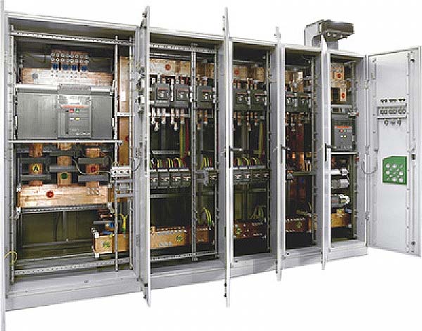
Главный распределительный щит (ГРЩ) на ток 6300 А
[http://www.uzoelectro.ru/catalogue/group-383/product-36465/ ]Тематики
- НКУ (шкафы, пульты,...)
- электроснабжение в целом
- электроустановки
Синонимы
EN
- feeder switchboard
- m.s.b.
- main distributing frame
- main distribution board
- main distribution switchboard
- Main Low Voltage Switchboard
- main low-voltage distribution switchboard
- main switchboard
- MLVS
- MSB
- power center
FR
Русско-французский словарь нормативно-технической терминологии > главный распределительный щит
-
3 сила тока
сила тока
—
[ http://www.eionet.europa.eu/gemet/alphabetic?langcode=en]EN
electric power
The rate at which electric energy is converted to other forms of energy, equal to the product of the current and the voltage drop. (Source: MGH)
[http://www.eionet.europa.eu/gemet/alphabetic?langcode=en]Тематики
EN
DE
FR
Русско-французский словарь нормативно-технической терминологии > сила тока
-
4 падение напряжения
1
падение напряжения
-
[IEV number 151-15-08]EN
voltage drop (1)
tension drop (1)
voltage between the terminals of a resistive element being part of an electric circuit due to the electric current through that element
[IEV number 151-15-08]FR
chute de tension (1), f
tension électrique produite aux bornes d’un élément résistif faisant partie d'un circuit électrique par le courant électrique qui circule dans cet élément
[IEV number 151-15-08]2
падение напряжения
-
[IEV number 151-15-09]EN
voltage drop (2)
tension drop (2)
change of the voltage between two given terminals of an electric circuit due to the change of the operating conditions
[IEV number 151-15-09]FR
chute de tension (2), f
variation de la tension électrique entre deux bornes données d'un circuit électrique due à une variation des conditions de fonctionnement
[IEV number 151-15-09]EN
DE
FR
Русско-французский словарь нормативно-технической терминологии > падение напряжения
-
5 шинопровод
система сборных шин
шинопровод
Устройство, представляющее собой систему проводников, состоящее из шин, установленных на опорах из изоляционного материала или в каналах, коробах или подобных оболочках, и прошедшее типовые испытания.
Устройство может состоять из следующих элементов:
- прямые секции с узлами ответвления или без них;
- секции для изменения положения фаз, разветвления, поворота, а также вводные и переходные;
- секции ответвленные.
Примечание — Термин «шинопровод» не определяет геометрическую форму, габариты и размеры проводников.
(МЭС 441-12-07, с изменением)
[ ГОСТ Р 51321. 1-2000 ( МЭК 60439-1-92)]
шинопровод
Жесткий токопровод до 1 кВ заводского изготовления, поставляемый комплектными секциями.
[ПУЭ]
шинопровод
Жесткий токопровод напряжением до 1000 В заводского изготовления, поставляемый комплектными секциями.
[ОСТ 36-115-85]
шинопровод
Жесткий токопровод напряжением до 1 кВ, предназначенный для передачи и распределения электроэнергии, состоящий из неизолированных или изолированных проводников (шин) и относящихся к ним изоляторов, защитных оболочек, ответвительных устройств, поддерживающих и опорных конструкций.
[ ГОСТ Р 53310-2012]EN
busway
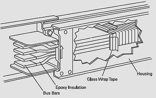
A prefabricated assembly of standard lengths of busbars rigidly supported by solid insulation and enclosed in a sheet-metal housing.
[ http://www.answers.com/topic/busway]
busway
Busway is defined by the National Electrical Manufacturers Association (NEMA) as a prefabricated electrical distribution system consisting of bus bars in a protective enclosure, including straight lengths, fittings, devices, and accessories. Busway includes bus bars, an insulating and/or support material, and a housing.
[ http://electrical-engineering-portal.com/siemens-busway-purpose-and-definition]1.1. Шинопроводы по назначению подразделяются на:
- распределительные, предназначенные для распределения электрической энергии;
- магистральные, предназначенные для передачи электрической энергии от источника к месту распределения (распределительным пунктам, распределительным шинопроводам) или мощным приемникам электрической энергии.
1.2. По конструктивному исполнению шинопроводы подразделяются на:
- трехфазные;
- трехфазные с нулевым рабочим проводником;
- трехфазные с нулевым рабочим и нулевым защитным проводником.
2. Основные параметры и размеры
2.1. Основные элементы шинопроводов
2.1.1. Основными элементами распределительных шинопроводов являются:а) прямые секции - для прямолинейных участков линии, имеющие места для присоединения одного или двух ответвительных устройств для секций длиной до 2 м включительно, двух, трех, четырех или более - для секций длиной 3 м;
б) прямые прогоночные секции - для прямолинейных участков линий, где присоединение ответвительных устройств не требуется;
в) угловые секции - для поворотов линии на 90° в горизонтальной и вертикальной плоскостях;
г) вводные секции или вводные коробки с коммутационной, защитной и коммутационной аппаратурой или без нее - для подвода питания к шинопроводам кабелем, проводами или шинопроводом;
д) переходные секции или устройства - для соединения двух шинопроводов на различные номинальные токи или шинопроводов разных конструкций;
е) ответвительные устройства (коробки, штепсели) - для разъемного присоединения приемников электрической энергии. Коробки должны выпускаться с разъединителем, с разъединителем и с предохранителями или с автоматическим выключателем;
з) присоединительные фланцы - для сочленения оболочек шинопроводов с оболочками щитов или шкафов;
и) торцовые крышки (заглушки) - для закрытия торцов крайних секций шинопровода;
к) устройства для крепления шинопроводов к элементам строительных конструкций зданий и сооружений;2.1.2. Основными элементами магистральных шинопроводов являются:
а) прямые секции - для прямолинейных участков линий;
б) угловые секции - для поворотов линий на 90° в горизонтальной и вертикальной плоскостях;
в) тройниковые секции - для разветвления в трех направлениях под углом 90° в горизонтальной и вертикальной плоскостях;
г) подгоночные секции - для подгонки линии шинопроводов до необходимой длины;
д) разделительные секции с разъединителем - для секционирования магистральных линий шинопроводов;
е) компенсационные секции - для компенсации температурных изменений длины линии шинопроводов;
ж) переходные секции - для соединения шинопроводов на разные номинальные токи;
з) ответвительные устройства (секции, коробки) - для неразборного, разборного или разъемного присоединения распределительных пунктов, распределительных шинопроводов или приемников электрической энергии. Коробки должны выпускаться с разъединителем, с разъединителем и предохранителями или с автоматическим выключателем; секции могут выпускаться без указанных аппаратов;
и) присоединительные секции - для присоединения шинопроводов к комплектным трансформаторным подстанциям;
к) проходные секции - для прохода через стены и перекрытия;
л) набор деталей и материалов для изолирования мест соединения секций шинопроводов с изолированными шинами;
м) устройства для крепления шинопроводов к элементам строительных конструкций зданий и сооружений;
н) крышки (заглушки) торцовые и угловые для закрытия торцов концевых секций шинопровода и углов.
2.2.3. В зависимости от вида проводников токопроводы подразделяются на гибкие (при использовании проводов) и жесткие (при использовании жестких шин).
Жесткий токопровод до 1 кВ заводского изготовления, поставляемый комплектными секциями, называется шинопроводом.
В зависимости от назначения шинопроводы подразделяются на:- магистральные, предназначенные в основном для присоединения к ним распределительных шинопроводов и силовых распределительных пунктов, щитов и отдельных мощных электроприемников;
- распределительные, предназначенные в основном для присоединения к ним электроприемников;
- троллейные, предназначенные для питания передвижных электроприемников;
- осветительные, предназначенные для питания светильников и электроприемников небольшой мощности.
[ПУЭ, часть 2]
[ http://electrical-engineering-portal.com/siemens-busway-purpose-and-definition]
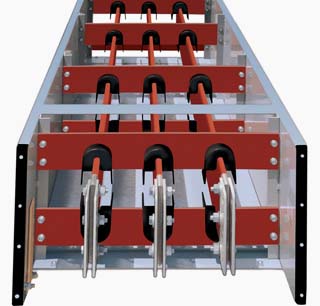
[ http://electrical-engineering-portal.com/standards-and-applications-of-medium-voltage-bus-duct]
Конструкция шинопровода на среднее напряжениеПараллельные тексты EN-RU
A major advantage of busway is the ease in which busway sections are connected together.
Electrical power can be supplied to any area of a building by connecting standard lengths of busway.
It typically takes fewer man-hours to install or change a busway system than cable and conduit assemblies.Основное преимущество шинопровода заключается в легкости соединения его секций.
Соединяя эти стандартные секции можно легко снабдить электроэнергией любую часть здания.
Как правило, установить или изменить систему шинопроводов занимает гораздо меньше времени, чем выполнить аналогичные работы, применяя разводку кабелем в защитных трубах.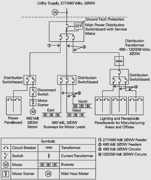
[ http://electrical-engineering-portal.com/siemens-busway-purpose-and-definition]
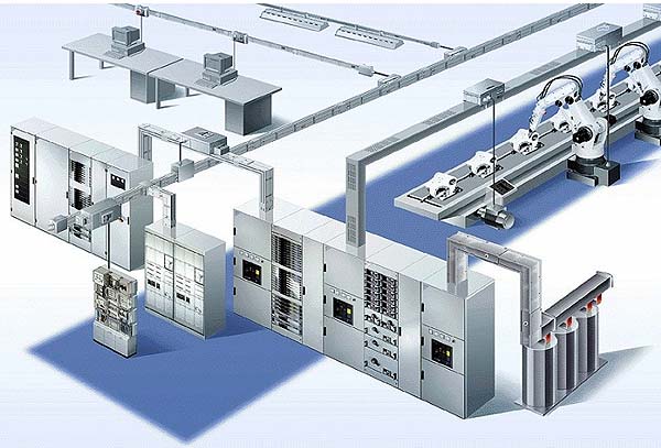
The total distribution system frequently consists of a combination of busway and cable and conduit.
In this example power from the utility company is metered and enters the plant through a distribution switchboard.
The switchboard serves as the main disconnecting means.Как правило, распределение электроэнергии производится как через шинопроводы, так и через проложенные в защитных трубах кабели.
В данном примере поступающая от питающей сети электроэнергия измеряется на вводе в главное распределительный щит (ГРЩ).
ГРЩ является главным коммутационным устройством.
The feeder on the left feeds a distribution switchboard, which in turn feeds a panelboard and a 480 volt, three-phase, three-wire (3Ø3W) motor.
Распределительная цепь, изображенная слева, питает распределительный щит, который в свою очередь питает групповой щиток и электродвигатель.
Электродвигатель получает питание через трехфазную трехпроводную линию напряжением 480 В.The middle feeder feeds another switchboard, which divides the power into three, three-phase, three-wire circuits. Each circuit feeds a busway run to 480 volt motors.
Средняя (на чертеже) распределительная цепь питает другой распределительный щит, от которого электроэнергия распределяется через три трехфазные трехпроводные линии на шинопроводы.
Каждый шинопровод используется для питания электродвигателей напряжением 480 В.The feeder on the right supplies 120/208 volt power, through a step-down transformer, to lighting and receptacle panelboards.
Распределительная цепь, изображенная справа, питает напряжением 120/208 В через понижающий трансформатор щитки для отдельных групп светильников и штепсельных розеток.
Branch circuits from the lighting and receptacle panelboards supply power for lighting and outlets throughout the plant.
[ http://electrical-engineering-portal.com/siemens-busway-purpose-and-definition]Групповые электрические цепи, идущие от групповых щитков, предназначены для питания всех светильников и штепсельных розеток предприятия.
[Перевод Интент]Selection of the busbar trunking system based on voltage drop.
[Legrand]Выбор шинопровода по падению напряжения.
[Перевод Интент]
Недопустимые, нерекомендуемые
Примечание(1)- Мнение автора карточкиТематики
- изделие электромонтажное
- электропроводка, электромонтаж
Обобщающие термины
Близкие понятия
- электропроводки, выполненные шинопроводами
Действия
- выбор шинопровода по...
- крепление шинопровода к опорным конструкциям
- монтаж шинопроводов
- применение шинопроводов в пожароопасных зонах
- проектирование шинопровода
- прокладка шинопровода
Сопутствующие термины
- вертикальный участок шинопровода
- горизонтальный участок шинопровода
- прямой участок шинопровода
- устройства для крепления шинопроводов
- шинопровод переменного тока на 1600 А
- электрическая сеть, выполняемая шинопроводами
EN
DE
FR
Русско-французский словарь нормативно-технической терминологии > шинопровод
-
6 длительный допустимый ток
- courant permanent admissible, m
- courant admissible, m
(длительный) допустимый ток
Максимальное значение электрического тока, который может протекать длительно по проводнику, устройству или аппарату при определенных условиях без превышения определенного значения их температуры в установившемся режиме
[ ГОСТ Р МЭК 60050-826-2009]
Этот ток обозначают IZ
[ ГОСТ Р 50571. 1-2009 ( МЭК 60364-1: 2005)]EN
(continuous) current-carrying capacity
ampacity (US)
maximum value of electric current which can be carried continuously by a conductor, a device or an apparatus, under specified conditions without its steady-state temperature exceeding a specified value
[IEV number 826-11-13]
ampacity
The current in amperes that a conductor can carry continuously under the conditions of use without exceeding its temperature rating.
[National Electrical Cod]FR
courant (permanent) admissible, m
valeur maximale du courant électrique qui peut parcourir en permanence, un conducteur, un dispositif ou un appareil, sans que sa température de régime permanent, dans des conditions données, soit supérieure à la valeur spécifiée
[IEV number 826-11-13]Ampacity, the term is defined as the maximum amount of current a cable can carry before sustaining immediate or progressive deterioration. Also described as current rating or current-carrying capacity, is the RMS electric current which a device can continuously carry while remaining within its temperature rating. The ampacity of a cable depends on:
- its insulation temperature rating;
- conductor electrical properties for current;
- frequency, in the case of alternating currents;
- ability to dissipate heat, which depends on cable geometry and its surroundings;
- ambient temperature.
Electric wires have some resistance, and electric current flowing through them causes voltage drop and power dissipation, which heats the cable. Copper or aluminum can conduct a large amount of current before melting, but long before the conductors melt, their insulation would be damaged by the heat.
The ampacity for a power cable is thus based on physical and electrical properties of the material & construction of the conductor and of its insulation, ambient temperature, and environmental conditions adjacent to the cable. Having a large overall surface area may dissipate heat well if the environment can absorb the heat.
In a long run of cable, different conditions govern, and installation regulations normally specify that the most severe condition along the run governs the cable's rating. Cables run in wet or oily locations may carry a lower temperature rating than in a dry installation. Derating is necessary for multiple circuits in close proximity. When multiple cables are near, each contributes heat to the others and diminishes the amount of cooling air that can flow past the individual cables. The overall ampacity of the insulated conductors in a bundle of more than 3 must be derated, whether in a raceway or cable. Usually the de-rating factor is tabulated in a nation's wiring regulations.
Depending on the type of insulating material, common maximum allowable temperatures at the surface of the conductor are 60, 75 and 90 degrees Celsius, often with an ambient air temperature of 30°C. In the U.S., 105°C is allowed with ambient of 40°C, for larger power cables, especially those operating at more than 2 kV. Likewise, specific insulations are rated 150, 200 or 250°C.
The allowed current in cables generally needs to be decreased (derated) when the cable is covered with fireproofing material.
For example, the United States National Electric Code, Table 310-16, specifies that up to three 8 AWG copper wires having a common insulating material (THWN) in a raceway, cable, or direct burial has an ampacity of 50 A when the ambient air is 30°C, the conductor surface temperature allowed to be 75°C. A single insulated conductor in air has 70 A rating.
Ampacity rating is normally for continuous current, and short periods of overcurrent occur without harm in most cabling systems. The acceptable magnitude and duration of overcurrent is a more complex topic than ampacity.
When designing an electrical system, one will normally need to know the current rating for the following:- Wires
- Printed Circuit Board traces, where included
- Fuses
- Circuit breakers
- All or nearly all components used
Some devices are limited by power rating, and when this power rating occurs below their current limit, it is not necessary to know the current limit to design a system. A common example of this is lightbulb holders.
[http://en.wikipedia.org/wiki/Ampacity]
Тематики
- электротехника, основные понятия
Синонимы
EN
DE
- Dauerstrombelastbarkeit, f
- Strombelastbarkeit, f
FR
- courant admissible, m
- courant permanent admissible, m
Русско-французский словарь нормативно-технической терминологии > длительный допустимый ток
См. также в других словарях:
Voltage drop — is the reduction in voltage in an electrical circuit between the source and load. In electrical wiring national and local electrical codes may set guidelines for maximum voltage drop allowed in a circuit, to ensure reasonable efficiency of… … Wikipedia
voltage drop — situation in which a sudden decrease in the intensity of the voltage occurs … English contemporary dictionary
Resistive Voltage Drop — The voltage developed across a cell by the current flow through the resistance of the cell … Energy terms
Resistive voltage drop — The voltage developed across a cell by the current flow through the resistance of the cell. Solar Electric Glossary … Energy terms
voltage drop — The lowering of voltage due to excess length of wire, undersize wire, etc … Dictionary of automotive terms
Voltage-to-current converter — Introduction For a variety of reasons, in low voltage electronics, voltage is a more frequently used data carrier. Thus electronic devices tend to be labeled with voltage inputs and outputs. However some devices are labeled in terms of current… … Wikipedia
Voltage — Potential difference redirects here. For other uses, see Potential. Working on high voltage power lines, Pearl Harbor … Wikipedia
Voltage multiplier — Villard cascade voltage multiplier. A voltage multiplier is an electrical circuit that converts AC electrical power from a lower voltage to a higher DC voltage, typically by means of a network of capacitors and diodes. Voltage multipliers can be… … Wikipedia
Voltage ladder — A voltage ladder is a simple electronic circuit consisting of several resistors connected in series with a voltage placed across the entire resistor network. Voltage ladders are useful for providing a set of successive voltage references, for… … Wikipedia
Voltage divider — In electronics, a voltage divider (also known as a potential divider) is a simple linear circuit that produces an output voltage ( V out) that is a fraction of its input voltage ( V in). Voltage division refers to the partitioning of a voltage… … Wikipedia
Voltage clamp — The voltage clamp is used by electrophysiologists to measure the ion currents across a neuronal membrane while holding the membrane voltage at a set level. Neuronal membranes contain many different kinds of ion channels, some of which are voltage … Wikipedia