-
81 switchboard
- распределительный щит
- распределительное устройство
- НКУ распределения и управления
- коммутационный щит
- коммутаторная панель
- коммутатор
коммутатор
Устройство, обеспечивающее посредством включения, отключения и переключения электрических цепей выбор требуемой выходной цепи и соединение с ней входной цепи
[Терминологический словарь по строительству на 12 языках (ВНИИИС Госстроя СССР)]Тематики
- аппарат, изделие, устройство...
EN
DE
FR
коммутаторная панель
распределительный щит
Устройство, конструктивно объединяющее несколько коммутационных элементов, предназначенных для включения, отключения и переключения электрических цепей и каналов связи в ручном режиме.
[Л.М. Невдяев. Телекоммуникационные технологии. Англо-русский толковый словарь-справочник. Под редакцией Ю.М. Горностаева. Москва, 2002]Тематики
- электросвязь, основные понятия
Синонимы
EN
коммутационный щит
—
[Я.Н.Лугинский, М.С.Фези-Жилинская, Ю.С.Кабиров. Англо-русский словарь по электротехнике и электроэнергетике, Москва, 1999 г.]Тематики
- электротехника, основные понятия
EN
низковольтное устройство распределения и управления (НКУ)
Низковольтные коммутационные аппараты и устройства управления, измерения, сигнализации, защиты, регулирования, собранные совместно, со всеми внутренними электрическими и механическими соединениями и конструктивными элементами.
[ ГОСТ Р МЭК 61439-1-2012]
низковольтное устройство распределения и управления
Комбинация низковольтных коммутационных аппаратов с устройствами управления, измерения, сигнализации, защиты, регулирования и т. п., полностью смонтированных изготовителем НКУ (под его ответственность на единой конструктивной основе) со всеми внутренними электрическими и механическими соединениями с соответствующими конструктивными элементами
Примечания
1. В настоящем стандарте сокращение НКУ используют для обозначения низковольтных комплектных устройств распределения и управления.
2. Аппараты, входящие в состав НКУ, могут быть электромеханическими или электронными.
3. По различным причинам, например по условиям транспортирования или изготовления, некоторые операции сборки могут быть выполнены на месте установки, вне предприятия-изготовителя.
[ ГОСТ Р 51321. 1-2000 ( МЭК 60439-1-92)]EN
power switchgear and controlgear assembly (PSC-assembly)
low-voltage switchgear and controlgear assembly used to distribute and control energy for all types of loads, intended for industrial, commercial and similar applications where operation by ordinary persons is not intended
[IEC 61439-2, ed. 1.0 (2009-01)]
low-voltage switchgear and controlgear assembly
combination of one or more low-voltage switching devices together with associated control, measuring, signalling, protective, regulation equipment, etc., completely assembled under the responsibility of the manufacturer with all the internal electrical and mechanical interconnections and structural parts.
[IEC 61892-3, ed. 2.0 (2007-11)]
switchgear and controlgear
a general term covering switching devices and their combination with associated control, measuring, protective and regulating equipment, also assemblies of such devices and equipment with associated interconnections, accessories, enclosures and supporting structures
[IEV number 441-11-01]
switchgear and controlgear
electric equipment intended to be connected to an electric circuit for the purpose of carrying out one or more of the following functions: protection, control, isolation, switching
NOTE – The French and English terms can be considered as equivalent in most cases. However, the French term has a broader meaning than the English term and includes for example connecting devices, plugs and socket-outlets, etc. In English, these latter devices are known as accessories.
[IEV number 826-16-03 ]
switchboard
A large single electric control panel, frame, or assembly of panels on which are mounted (either on the back or on the face, or both) switches, overcurrent and other protective devices, buses, and usually instruments; not intended for installation in a cabinet but may be completely enclosed in metal; usually is accessible from both the front and rear.
[ McGraw-Hill Dictionary of Architecture & Construction]
switchboard
One or more panels accommodating control switches, indicators, and other apparatus for operating electric circuits
[ The American Heritage Dictionary of the English Language]FR
ensemble d'appareillage de puissance (ensemble PSC)
ensemble d'appareillage à basse tension utilisé pour répartir et commander l'énergie pour tous les types de charges et prévu pour des applications industrielles, commerciales et analogues dans lesquelles l'exploitation par des personnes ordinaires n'est pas prévue
[IEC 61439-2, ed. 1.0 (2009-01)]
appareillage, m
matériel électrique destiné à être relié à un circuit électrique en vue d'assurer une ou plusieurs des fonctions suivantes: protection, commande, sectionnement, connexion
NOTE – Les termes français et anglais peuvent être considérés comme équivalents dans la plupart des cas. Toutefois, le terme français couvre un domaine plus étendu que le terme anglais, et comprend notamment les dispositifs de connexion, les prises de courant, etc. En anglais, ces derniers sont dénommés "accessories".
[IEV number 826-16-03 ]
appareillage
terme général applicable aux appareils de connexion et à leur combinaison avec des appareils de commande, de mesure, de protection et de réglage qui leur sont associés, ainsi qu'aux ensembles de tels appareils avec les connexions, les accessoires, les enveloppes et les charpentes correspondantes
[IEV number 441-11-01]
A switchboard as defined in the National Electrical Code is a large single panel, frame, or assembly of panels on which are mounted, on the face or back or both switches, overcurrent and other protective devices, buses, and, usually, instruments.
Switchboards are generally accessible from the rear as well as from the front and are not intended to be installed in cabinets.
The types of switchboards, classified by basic features of construction, are as follows:
1. Live-front vertical panels
2. Dead-front boards
3. Safety enclosed boards( metal-clad)
[American electricians’ handbook]
The switchboard plays an essential role in the availability of electric power, while meeting the needs of personal and property safety.
Its definition, design and installation are based on precise rules; there is no place for improvisation.
The IEC 61439 standard aims to better define " low-voltage switchgear and controlgear assemblies", ensuring that the specified performances are reached.
It specifies in particular:
> the responsibilities of each player, distinguishing those of the original equipment manufacturer - the organization that performed the original design and associated verification of an assembly in accordance with the standard, and of the assembly manufacturer - the organization taking responsibility for the finished assembly;
> the design and verification rules, constituting a benchmark for product certification.
All the component parts of the electrical switchboard are concerned by the IEC 61439 standard.
Equipment produced in accordance with the requirements of this switchboard standard ensures the safety and reliability of the installation.
A switchboard must comply with the requirements of standard IEC 61439-1 and 2 to guarantee the safety and reliability of the installation.
Managers of installations, fully aware of the professional and legal liabilities weighing on their company and on themselves, demand a high level of safety for the electrical installation.
What is more, the serious economic consequences of prolonged halts in production mean that the electrical switchboard must provide excellent continuity of service, whatever the operating conditions.
[Schneider Electric]НКУ играет главную роль в обеспечении электроэнергией, удовлетворяя при этом всем требованиям по безопасности людей и сохранности имущества.
Выбор конструкции, проектирование и монтаж основаны на чётких правилах, не допускающих никакой импровизации.
Требования к низковольтным комплектным устройствам распределения и управления сформулированы в стандарте МЭК 61439 (ГОСТ Р 51321. 1-2000).
В частности, он определяет:
> распределение ответственности между изготовителем НКУ - организацией, разработавшей конструкцию НКУ и проверившей его на соответствие требованиям стандарта, и сборщиком – организацией, выполнившей сборку НКУ;
> конструкцию, технические характеристики, виды и методы испытаний НКУ.
В стандарте МЭК 61439 (ГОСТ Р 51321. 1-2000) описываются все компоненты НКУ.
Оборудование, изготовленное в соответствии с требованиями этого стандарта, обеспечивает безопасность и надежность электроустановки.
Для того чтобы гарантировать безопасность эксплуатации и надежность работы электроустановки, распределительный щит должен соответствовать требованиям стандарта МЭК 61439-1 и 2.
Лица, ответственные за электроустановки, должны быть полностью осведомлены о профессиональной и юридической ответственности, возложенной на их компанию и на них лично, за обеспечение высокого уровня безопасности эксплуатации этих электроустановок.
Кроме того, поскольку длительные перерывы производства приводят к серьезным экономическим последствиям, электрический распределительный щит должен обеспечивать надежную и бесперебойную работу независимо от условий эксплуатации.
[Перевод Интент]LV switchgear assemblies are undoubtedly the components of the electric installation more subject to the direct intervention of personnel (operations, maintenance, etc.) and for this reason users demand from them higher and higher safety requirements.
The compliance of an assembly with the state of the art and therefore, presumptively, with the relevant technical Standard, cannot be based only on the fact that the components which constitute it comply with the state of the art and therefore, at least presumptively, with the relevant technical standards.
In other words, the whole assembly must be designed, built and tested in compliance with the state of the art.
Since the assemblies under consideration are low voltage equipment, their rated voltage shall not exceed 1000 Va.c. or 1500 Vd.c. As regards currents, neither upper nor lower limits are provided in the application field of this Standard.
The Standard IEC 60439-1 states the construction, safety and maintenance requirements for low voltage switchgear and controlgear assemblies, without dealing with the functional aspects which remain a competence of the designer of the plant for which the assembly is intended.
[ABB]Низковольтные комплектные устройства (НКУ), вне всякого сомнения, являются частями электроустановок, которые наиболее подвержены непосредственному вмешательству оперативного, обслуживающего и т. п. персонала. Вот почему требования потребителей к безопасности НКУ становятся все выше и выше.
Соответствие НКУ современному положению дел и вследствие этого, гипотетически, соответствующим техническим стандартам, не может основываться только на том факте, что составляющие НКУ компоненты соответствуют современному состоянию дел и поэтому, по крайней мере, гипотетически, - соответствующим техническим стандартам
Другими словами, НКУ должно быть разработано, изготовлено и испытано в соответствии с современными требованиями.
Мы рассматриваем низковольтные комплектные устройства и это означает, что их номинальное напряжение не превышает 1000 В переменного тока или 1500 В постоянного тока. Что касается тока, то ни верхнее, ни нижнее значение стандартами, относящимися к данной области, не оговариваются
Стандарт МЭК 60439-1 устанавливает требования к конструкции, безопасности и техническому обслуживанию низковольтных комплектных устройств без учета их функций, полагая, что функции НКУ являются компетенцией проектировщиков электроустановки, частью которых эти НКУ являются.
[Перевод Интент]Тематики
- НКУ (шкафы, пульты,...)
Классификация
>>>Действия
Синонимы
Сопутствующие термины
EN
- assembly
- electrical switchboard
- low voltage controlgear and assembly
- low voltage switchboard
- low voltage switchgear and controlgear assembly
- low-voltage switchgear and controlgear assembly
- LV switchgear and controlgear assembly
- LV switchgear assembly
- panel
- power switchgear and controlgear assembly
- PSC-assembly
- switchboard
- switchgear and controlgear
- switchgear/controlgear
DE
- Schaltanlagen und/oder Schaltgeräte
FR
распределительное устройство
Распределительным устройством (РУ) называется электроустановка, служащая для приема и распределения электроэнергии и содержащая сборные и соединительные шины, коммутационные аппараты, вспомогательные устройства (компрессорные, аккумуляторные и др.), а также устройства защиты, автоматики и измерительные приборы.
[РД 34.20.185-94]
распределительное устройство
Электроустановка, предназначенная для приема и распределения электрической энергии на одном напряжении и содержащая коммутационные аппараты и соединяющие их сборные шины [секции шин], устройства управления и защиты.
Примечание. К устройствам управления относятся аппараты и связывающие их элементы обеспечивающие контроль, измерение, сигнализацию и выполнение команд.
[ ГОСТ 24291-90]
[ ГОСТ Р 53685-2009]
электрическое распределительное устройство
распределительное устройство
Устройство, предназначенное для приема и распределения электроэнергии на одном напряжении и содержащее коммутационные аппараты и соединяющие их сборные соединительные устройства.
Примечание. В состав распределительного устройства дополнительно могут входить устройства защиты и управления
[ОСТ 45.55-99]
распределительное устройство
Электроустановка, служащая для приема и распределения электроэнергии и содержащая коммутационные аппараты, сборные и соединительные шины, вспомогательные устройства (компрессорные, аккумуляторные и др.), а также устройства защиты, автоматики и измерительные приборы.
[ПОТ Р М-016-2001]
[РД 153-34.0-03.150-00]
устройство распределительное
Совокупность аппаратов и приборов для приёма и распределения электроэнергии одного напряжения, вырабатываемой электростанцией или преобразуемой подстанцией
[Терминологический словарь по строительству на 12 языках (ВНИИИС Госстроя СССР)]EN
switching substation
a substation which includes switchgear and usually busbars, but no power transformers
[IEV number 605-01-02]FR
poste de sectionnement
poste de coupure
poste comprenant des organes de manoeuvre et généralement des jeux de barres, à l'exclusion de transformateurs de puissance
[IEV number 605-01-02]В качестве РУ 6—10 кВ используется сборка высокого напряжения с однополюсными разъединителями и вертикальным расположением фаз одного присоединения и одна камера КСО с выключателем нагрузки и предохранителями для подключения трансформатора. Для РУ 0,4 кВ применяются сборки низкого напряжения с предохранителями и вертикальным расположением фаз одного присоединения.
На ПС применяются открытые (ОРУ), закрытые (ЗРУ) или комплектные (КРУ) распределительные устройства.
[ http://energy-ua.com/elektricheskie-p/klassifikatsiya.html]
В общем случае ПС и РУ являются составной частью электроустановок, которые различаются:
-
по назначению:
- генерирующие,
- преобразовательно-распределительные,
-
потребительские.
Генерирующие электроустановки служат для выработки электроэнергии, преобразовательно-распределительные электроустановки преобразуют электроэнергию в удобный для передачи и потребления вид, передают ее и распределяют между потребителями;
-
по роду тока:
- постоянного тока,
- переменного тока.
-
по напряжению:
- до 1000 В,
- выше 1000 В.
Шкала номинальных напряжений ограничена сравнительно небольшим числом стандартных значений, благодаря чему изготавливается небольшое число типоразмеров машин и оборудования, а электросети выполняются более экономичными. В установках трехфазного тока номинальным напряжением принято считать напряжение между фазами (междуфазовое напряжение). Согласно ГОСТ 29322—92 установлена следующая шкала номинальных напряжений:
для электросетей переменного тока частотой 50 Гц междуфазовое напряжение должно быть: 12, 24, 36, 42, 127, 220, 380 В; 3, 6, 10, 20, 35, 110, 150, 220, 330, 500, 750 и 1150 кВ;
для электросетей постоянного тока: 12, 24, 36, 48, 60, 110, 220, 440, 660, 825, 3000 В и выше.-
по способу присоединения к электросети ПС разделяются на:
- тупиковые (блочные),
- ответвительные (блочные),
- проходные (транзитные)
- узловые.
Тупиковые ПС получают питание по одной или двум тупиковым ВЛ.
Ответвительные ПС присоединяются ответвлением к одной или двум проходящим ВЛ с односторонним или двухсторонним питанием.
Проходные ПС включаются в рассечку одной или двух проходящих ВЛ с односторонним или двухсторонним питанием.
Узловые ПС кроме питающих имеют отходящие радиальные или транзитные ВЛ.-
по способу управления ПС могут быть:
- только с телесигнализацией,
- телеуправляемыми с телесигнализацией,
- с телесигнализацией и управлением с общеподстанционного пункта управления (ОПУ).
Подстанции оперативно обслуживаются постоянным дежурным персоналом на щите управления, дежурными на дому или оперативно-выездными бригадами (ОВБ). Ремонт ПС осуществляется специализированными выездными бригадами централизованного ремонта или местным персоналом подстанции.
В РУ напряжением до 1000 В провода, шины, аппараты, приборы и конструкции выбирают как по нормальным условиям работы (напряжению и току), так и по термическим и динамическим воздействиям токов коротких замыканий (КЗ) или предельно допустимой отключаемой мощности.
В РУ и ПС напряжением выше 1000 В расстояния между электрооборудованием, аппаратами, токоведущими частями, изоляторами, ограждениями и конструкциями устанавливаются так, чтобы при нормальном режиме работы электроустановки возникающие физические явления (температура нагрева, электрическая дуга, выброс газов, искрение и др.) не могли привести к повреждению оборудования и КЗ.[ http://energy-ua.com/elektricheskie-p/klassifikatsiya.html]
Several different classifications of switchgear can be made:- By the current rating.
-
By interrupting rating (maximum short circuit current that the device can safely interrupt)
- Circuit breakers can open and close on fault currents
- Load-break/Load-make switches can switch normal system load currents
- Isolators may only be operated while the circuit is dead, or the load current is very small.
-
By voltage class:
- Low voltage (less than 1,000 volts AC)
- Medium voltage (1,000–35,000 volts AC)
- High voltage (more than 35,000 volts AC)
-
By insulating medium:
-
By construction type:
- Indoor (further classified by IP (Ingress Protection) class or NEMA enclosure type)
- Outdoor
- Industrial
- Utility
- Marine
- Draw-out elements (removable without many tools)
- Fixed elements (bolted fasteners)
- Live-front
- Dead-front
- Open
- Metal-enclosed
- Metal-clad
- Metal enclosed & Metal clad
- Arc-resistant
-
By IEC degree of internal separation
- No Separation (Form 1)
- Busbars separated from functional units (Form 2a, 2b, 3a, 3b, 4a, 4b)
- Terminals for external conductors separated from busbars (Form 2b, 3b, 4a, 4b)
- Terminals for external conductors separated from functional units but not from each other (Form 3a, 3b)
- Functional units separated from each other (Form 3a, 3b, 4a, 4b)
- Terminals for external conductors separated from each other (Form 4a, 4b)
- Terminals for external conductors separate from their associated functional unit (Form 4b)
-
By interrupting device:
-
By operating method:
- Manually operated
- Motor/stored energy operated
- Solenoid operated
-
By type of current:
-
By application:
-
By purpose
- Isolating switches (disconnectors)
- Load-break switches.
- Grounding (earthing) switches
A single line-up may incorporate several different types of devices, for example, air-insulated bus, vacuum circuit breakers, and manually operated switches may all exist in the same row of cubicles.
Ratings, design, specifications and details of switchgear are set by a multitude of standards. In North America mostly IEEE and ANSI standards are used, much of the rest of the world uses IEC standards, sometimes with local national derivatives or variations.
[Robert W. Smeaton (ed) Switchgear and Control Handbook 3rd Ed., Mc Graw Hill, new York 1997]
[ http://en.wikipedia.org/wiki/High_voltage_switchgear]Тематики
- электрификация, электроснабж. железных дорог
- электроагрегаты генераторные
- электробезопасность
- электроснабжение в целом
Синонимы
EN
- distribution
- energy distribution board
- gear
- switch-gear
- switchboard
- switchgear
- switching substation
- switchyard
DE
FR
распределительный щит
Комплектное устройство, содержащее различную коммутационную аппаратуру, соединенное с одной или более отходящими электрическими цепями, питающееся от одной или более входящих цепей, вместе с зажимами для присоединения нейтральных и защитных проводников.
[ ГОСТ Р МЭК 60050-826-2009]
щит распределительный
Электротехническое устройство, объединяющее коммутационную, регулирующую и защитную аппаратуру, а также контрольно-измерительные и сигнальные приборы
[Терминологический словарь по строительству на 12 языках (ВНИИИС Госстроя СССР)]
распределительный щит
—
[А.С.Гольдберг. Англо-русский энергетический словарь. 2006 г.]EN
distribution board
assembly containing different types of switchgear and controlgear associated with one or more outgoing electric circuits fed from one or more incoming electric circuits, together with terminals for the neutral and protective conductors.
[IEV number 826-16-08]FR
tableau de répartition, m
ensemble comportant différents types d'appareillage associés à un ou plusieurs circuits électriques de départ alimentés par un ou plusieurs circuits électriques d'arrivée, ainsi que des bornes pour les conducteurs neutre et de protection.
[IEV number 826-16-08]Distribution switchboards, including the Main LV Switchboard (MLVS), are critical to the dependability of an electrical installation. They must comply with well-defined standards governing the design and construction of LV switchgear assemblies
A distribution switchboard is the point at which an incoming-power supply divides into separate circuits, each of which is controlled and protected by the fuses or switchgear of the switchboard. A distribution switchboard is divided into a number of functional units, each comprising all the electrical and mechanical elements that contribute to the fulfilment of a given function. It represents a key link in the dependability chain.
Consequently, the type of distribution switchboard must be perfectly adapted to its application. Its design and construction must comply with applicable standards and working practises.
[Schneider Electric]Распределительные щиты, включая главный распределительный щит низкого напряжения (ГРЩ), играют решающую роль в обеспечении надежности электроустановки. Они должны отвечать требованиям соответствующих стандартов, определяющих конструкцию и порядок изготовления НКУ распределения электроэнергии.
В распределительном щите выполняется прием электроэнергии и ее распределение по отдельным цепям, каждая из которых контролируется и защищается плавкими предохранителями или автоматическими выключателями.
Распределительный щит состоит из функциональных блоков, включающих в себя все электрические и механические элементы, необходимые для выполнения требуемой функции. Распределительный щит представляет собой ключевое звено в цепи обеспечения надежности.
Тип распределительного щита должен соответствовать области применения. Конструкция и изготовление распределительного щита должны удовлетворять требованиям применимых стандартов и учитывать накопленную практику применения.
[Перевод Интент]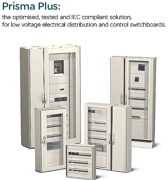
Рис. Schneider Electric
With Prisma Plus G you can be sure to build 100% Schneider Electric switchboards that are safe, optimised:
> All components (switchgear, distribution blocks, prefabricated connections, etc.) are perfectly rated and coordinated to work together;
> All switchboard configurations, even the most demanding ones, have been tested.
You can prove that your switchboard meets the current standards, at any time.
You can be sure to build a reliable electrical installation and give your customers full satisfaction in terms of dependability and safety for people and the installation.
Prisma Plus G with its discreet design, blends harmoniously into all tertiary and industrial buildings, including in entrance halls and passageways.
With Prisma Plus G you can build just the right switchboard for your customer, sized precisely to fit costs and needs.
With this complete, prefabricated and tested system, it's easy to upgrade your installation and still maintain the performance levels.
> The wall-mounted and floor-standing enclosures combine easily with switchboards already in service.
> Devices can be replaced or added at any time.
[Schneider Electric]С помощью оболочек Prisma Plus G можно создавать безопасные распределительные щиты, на 100 % состоящие из изделий Schneider Electric:
> все изделия (коммутационная аппаратура, распределительные блоки, готовые заводские соединения и т. д.) полностью совместимы механически и электрически;
> все варианты компоновки распределительных щитов, в том числе для наиболее ответственных применений, прошли испытания.В любое время вы можете доказать, что ваши распределительные щиты полностью соответствуют требованиям действующих стандартов.
Вы можете быть полностью уверены в том, что создаете надежные электроустановки, удовлетворяющие всем требованиям безопасности для людей и оборудования
Благодаря строгому дизайну, распределительные щиты Prisma Plus G гармонично сочетаются с интерьером любого общественного или промышленного здания. Они хорошо смотрятся и в вестибюле, и в коридоре.
Применяя оболочки Prisma Plus G можно создавать распределительные щиты, точно соответствующие требованиям заказчика как с точки зрения технических характеристик, так и стоимости.
С помощью данной испытанной системы, содержащей все необходимые компоненты заводского изготовления можно легко модернизировать существующую электроустановку и поддерживать её уровни производительности.> Навесные и напольные оболочки можно легко присоединить к уже эксплуатируемым распределительным щитам.
> Аппаратуру можно заменять или добавлять в любое время.
[Перевод Интент]The switchboard, central to the electrical installation.
Both the point of arrival of energy and a device for distribution to the site applications, the LV switchboard is the intelligence of the system, central to the electrical installation.
[Schneider Electric]Распределительный щит – «сердце» электроустановки.
Низковольтное комплектное устройство распределения является «сердцем» электроустановки, поскольку именно оно принимает электроэнергию из сети и распределяет её по территориально распределенным нагрузкам.
[Перевод Интент]Тематики
- НКУ (шкафы, пульты,...)
- электроснабжение в целом
EN
- branch distribution panel
- distributing board
- distributing panel
- distributing switchboard
- distribution bench
- distribution board
- distribution panel
- distribution switchboard
- gear
- keyboard
- PNL
- SB
- sw & d
- switchboard
- switchboard panel
DE
- elektrischer Verteiler, m
- Schalttafel
- Verteiler, m
FR
- tableau de distribution
- tableau de répartition, m
Англо-русский словарь нормативно-технической терминологии > switchboard
-
82 model
['modl] 1. noun1) (a copy or representation of something usually on a much smaller scale: a model of the Taj Mahal; ( also adjective) a model aeroplane.) model; -model; model-2) (a particular type or design of something, eg a car, that is manufactured in large numbers: Our car is a 1999 model.) model; -model3) (a person who wears clothes etc so that possible buyers can see them being worn: He has a job as a male fashion model.) model4) (a person who is painted, sculpted, photographed etc by an artist, photographer etc: I work as an artist's model.) model5) (something that can be used to copy from.) model6) (a person or thing which is an excellent example: She is a model of politeness; ( also adjective) model behaviour.) forbillede; forbilledlig2. verb1) (to wear (clothes etc) to show them to possible buyers: They model (underwear) for a living.) være model2) (to work or pose as a model for an artist, photographer etc: She models at the local art school.) stå model3) (to make models (of things or people): to model (the heads of famous people) in clay.) modellere; forme4) (to form (something) into a (particular) shape: She modelled the clay into the shape of a penguin; She models herself on her older sister.) forme; efterligne•* * *['modl] 1. noun1) (a copy or representation of something usually on a much smaller scale: a model of the Taj Mahal; ( also adjective) a model aeroplane.) model; -model; model-2) (a particular type or design of something, eg a car, that is manufactured in large numbers: Our car is a 1999 model.) model; -model3) (a person who wears clothes etc so that possible buyers can see them being worn: He has a job as a male fashion model.) model4) (a person who is painted, sculpted, photographed etc by an artist, photographer etc: I work as an artist's model.) model5) (something that can be used to copy from.) model6) (a person or thing which is an excellent example: She is a model of politeness; ( also adjective) model behaviour.) forbillede; forbilledlig2. verb1) (to wear (clothes etc) to show them to possible buyers: They model (underwear) for a living.) være model2) (to work or pose as a model for an artist, photographer etc: She models at the local art school.) stå model3) (to make models (of things or people): to model (the heads of famous people) in clay.) modellere; forme4) (to form (something) into a (particular) shape: She modelled the clay into the shape of a penguin; She models herself on her older sister.) forme; efterligne• -
83 relief
[rə'li:f]1) (a lessening or stopping of pain, worry, boredom etc: When one has a headache, an aspirin brings relief; He gave a sigh of relief; It was a great relief to find nothing had been stolen.) lettelse2) (help (eg food) given to people in need of it: famine relief; ( also adjective) A relief fund has been set up to send supplies to the refugees.) nødhjælp; nødhjælps-3) (a person who takes over some job or task from another person, usually after a given period of time: The bus-driver was waiting for his relief; ( also adjective) a relief driver.) afløsning; afløsnings-4) (the act of freeing a town etc from siege: the relief of Mafeking.) befrielse5) (a way of carving etc in which the design is raised above the level of its background: a carving in relief.) reliefarbejde•- relieve- relieved* * *[rə'li:f]1) (a lessening or stopping of pain, worry, boredom etc: When one has a headache, an aspirin brings relief; He gave a sigh of relief; It was a great relief to find nothing had been stolen.) lettelse2) (help (eg food) given to people in need of it: famine relief; ( also adjective) A relief fund has been set up to send supplies to the refugees.) nødhjælp; nødhjælps-3) (a person who takes over some job or task from another person, usually after a given period of time: The bus-driver was waiting for his relief; ( also adjective) a relief driver.) afløsning; afløsnings-4) (the act of freeing a town etc from siege: the relief of Mafeking.) befrielse5) (a way of carving etc in which the design is raised above the level of its background: a carving in relief.) reliefarbejde•- relieve- relieved -
84 radical
1. adjective1) (thorough, drastic; also Polit.) radikal; drastisch, radikal [Maßnahme]; umwälzend [Auswirkungen]; durchgreifend [Umstrukturierung, Veränderung usw.]2) (progressive, unorthodox) radikal; revolutionär [Stil, Design, Sprachgebrauch]3) (inherent, fundamental) grundlegend [Fehler, Unterschied]2. noun(Polit.) Radikale, der/die* * *['rædikəl] 1. adjective1) (relating to the basic nature of something: radical faults in the design.) fundamental2) (thorough; complete: radical changes.) drastisch3) (wanting or involving great or extreme political, social or economic changes.) radikal2. noun(a person who wants radical political changes.) der/die Radikale- academic.ru/59968/radically">radically* * *radi·cal[ˈrædɪkəl]I. adj1. POL radikal\radical activist radikaler Aktivist/radikale Aktivistin\radical bookshop/newspaper radikaler Buchladen/radikale Zeitung\radical feminist radikale Feministinthe \radical left/right die radikale [o äußerste] Linke/Rechte\radical views radikale [o extreme] Ansichtenthe \radical wing of the party der radikale Parteiflügel2. (fundamental) fundamental, totalwe need to take a \radical look at our operating procedures wir müssen unsere Vorgehensweise nochmals eingehend überprüfento make some \radical changes tiefgreifende [o weitreichende] Veränderungen vornehmen\radical difference grundlegender [o fundamentaler] Unterschied\radical measures tiefgreifende [o grundlegende] Maßnahmena \radical restructuring of a company eine völlige Umstrukturierung einer Firmaa \radical transformation ein grundlegender Wandel3. MED radikal\radical surgery Radikaloperation fto undergo \radical surgery sich akk einer Totaloperation unterziehenII. nleft-wing \radical radikale(r) Linke(r) f(m)right-wing \radical radikale(r) Rechte(r) f(m)* * *['rdIkəl]1. adj1) (= basic) fundamental, Grund-; difference, error fundamental; (= extreme) change, reform radikal, grundlegend; rethinking, re-examination total; measures einschneidend, radikal; reduction radikal, fundamental, rigoros2. n (POL)Radikale(r) mf; (MATH, GRAM) Wurzel f; (in Chinese) Radikal m; (CHEM) Radikal nt* * *radical [ˈrædıkl]radical cure Radikal-, Rosskur f;undergo a radical change sich von Grund auf ändern2. radikal, drastisch (Maßnahmen etc)3. a) fundamental, grundlegend(Unterschied etc)b) eingewurzelt, ursprünglich:the radical evil das Grund- oder Erbübel4. BOT, MATH Wurzel…:5. LING Wurzel…, Stamm…:radical bass Grundbass m;radical cadence Grundkadenz f8. CHEM Radikal…:radical chain (reaction) Radikalkette fB s2. MATHa) Wurzel fb) Wurzelzeichen n3. MUS Grundton m (eines Akkords)4. LING Wurzel(buchstabe) f(m)5. CHEM Radikal n6. fig Basis f, Grundlage fR abk5. Royal Kgl.rad. abk1. radiator3. radius4. radix* * *1. adjective1) (thorough, drastic; also Polit.) radikal; drastisch, radikal [Maßnahme]; umwälzend [Auswirkungen]; durchgreifend [Umstrukturierung, Veränderung usw.]2) (progressive, unorthodox) radikal; revolutionär [Stil, Design, Sprachgebrauch]3) (inherent, fundamental) grundlegend [Fehler, Unterschied]2. noun(Polit.) Radikale, der/die* * *(linguistics) n.Wurzelwort n. adj.gründlich adj.radikal adj. -
85 Arnold, John
SUBJECT AREA: Horology[br]b. 1735/6 Bodmin (?), Cornwall, Englandd. 25 August 1799 Eltham, London, England[br]English clock, watch, and chronometer maker who invented the isochronous helical balance spring and an improved form of detached detent escapement.[br]John Arnold was apprenticed to his father, a watchmaker, and then worked as an itinerant journeyman in the Low Countries and, later, in England. He settled in London in 1762 and rapidly established his reputation at Court by presenting George III with a miniature repeating watch mounted in a ring. He later abandoned the security of the Court for a more precarious living developing his chronometers, with some financial assistance from the Board of Longitude. Symbolically, in 1771 he moved from the vicinity of the Court at St James's to John Adam Street, which was close to the premises of the Royal Society for the Encouragement of Arts, Manufactures \& Commerce.By the time Arnold became interested in chronometry, Harrison had already demonstrated that longitude could be determined by means of a timekeeper, and the need was for a simpler instrument that could be sold at an affordable price for universal use at sea. Le Roy had shown that it was possible to dispense with a remontoire by using a detached escapement with an isochronous balance; Arnold was obviously thinking along the same lines, although he may not have been aware of Le Roy's work. By 1772 Arnold had developed his detached escapement, a pivoted detent which was quite different from that used on the European continent, and three years later he took out a patent for a compensation balance and a helical balance spring (Arnold used the spring in torsion and not in tension as Harrison had done). His compensation balance was similar in principle to that described by Le Roy and used riveted bimetallic strips to alter the radius of gyration of the balance by moving small weights radially. Although the helical balance spring was not completely isochronous it was a great improvement on the spiral spring, and in a later patent (1782) he showed how it could be made more truly isochronous by shaping the ends. In this form it was used universally in marine chronometers.Although Arnold's chronometers performed well, their long-term stability was less satisfactory because of the deterioration of the oil on the pivot of the detent. In his patent of 1782 he eliminated this defect by replacing the pivot with a spring, producing the spring detent escapement. This was also done independendy at about the same time by Berthoud and Earnshaw, although Earnshaw claimed vehemently that Arnold had plagiarized his work. Ironically it was Earnshaw's design that was finally adopted, although he had merely replaced Arnold's pivoted detent with a spring, while Arnold had completely redesigned the escapement. Earnshaw also improved the compensation balance by fusing the steel to the brass to form the bimetallic element, and it was in this form that it began to be used universally for chronometers and high-grade watches.As a result of the efforts of Arnold and Earnshaw, the marine chronometer emerged in what was essentially its final form by the end of the eighteenth century. The standardization of the design in England enabled it to be produced economically; whereas Larcum Kendall was paid £500 to copy Harrison's fourth timekeeper, Arnold was able to sell his chronometers for less than one-fifth of that amount. This combination of price and quality led to Britain's domination of the chronometer market during the nineteenth century.[br]Bibliography30 December 1775, "Timekeepers", British patent no. 1,113.2 May 1782, "A new escapement, and also a balance to compensate the effects arising from heat and cold in pocket chronometers, and for incurving the ends of the helical spring…", British patent no. 1,382.Further ReadingR.T.Gould, 1923, The Marine Chronometer: Its History and Development, London; reprinted 1960, Holland Press (provides an overview).V.Mercer, 1972, John Arnold \& Son Chronometer Makers 1726–1843, London.See also: Phillips, EdouardDV -
86 Evans, Oliver
SUBJECT AREA: Agricultural and food technology[br]b. 13 September 1755 Newport, Delaware, USAd. 15 April 1819 New York, USA[br]American millwright and inventor of the first automatic corn mill.[br]He was the fifth child of Charles and Ann Stalcrop Evans, and by the age of 15 he had four sisters and seven brothers. Nothing is known of his schooling, but at the age of 17 he was apprenticed to a Newport wheelwright and wagon-maker. At 19 he was enrolled in a Delaware Militia Company in the Revolutionary War but did not see active service. About this time he invented a machine for bending and cutting off the wires in textile carding combs. In July 1782, with his younger brother, Joseph, he moved to Tuckahoe on the eastern shore of the Delaware River, where he had the basic idea of the automatic flour mill. In July 1782, with his elder brothers John and Theophilus, he bought part of his father's Newport farm, on Red Clay Creek, and planned to build a mill there. In 1793 he married Sarah Tomlinson, daughter of a Delaware farmer, and joined his brothers at Red Clay Creek. He worked there for some seven years on his automatic mill, from about 1783 to 1790.His system for the automatic flour mill consisted of bucket elevators to raise the grain, a horizontal screw conveyor, other conveying devices and a "hopper boy" to cool and dry the meal before gathering it into a hopper feeding the bolting cylinder. Together these components formed the automatic process, from incoming wheat to outgoing flour packed in barrels. At that time the idea of such automation had not been applied to any manufacturing process in America. The mill opened, on a non-automatic cycle, in 1785. In January 1786 Evans applied to the Delaware legislature for a twenty-five-year patent, which was granted on 30 January 1787 although there was much opposition from the Quaker millers of Wilmington and elsewhere. He also applied for patents in Pennsylvania, Maryland and New Hampshire. In May 1789 he went to see the mill of the four Ellicot brothers, near Baltimore, where he was impressed by the design of a horizontal screw conveyor by Jonathan Ellicot and exchanged the rights to his own elevator for those of this machine. After six years' work on his automatic mill, it was completed in 1790. In the autumn of that year a miller in Brandywine ordered a set of Evans's machinery, which set the trend toward its general adoption. A model of it was shown in the Market Street shop window of Robert Leslie, a watch-and clockmaker in Philadelphia, who also took it to England but was unsuccessful in selling the idea there.In 1790 the Federal Plant Laws were passed; Evans's patent was the third to come within the new legislation. A detailed description with a plate was published in a Philadelphia newspaper in January 1791, the first of a proposed series, but the paper closed and the series came to nothing. His brother Joseph went on a series of sales trips, with the result that some machinery of Evans's design was adopted. By 1792 over one hundred mills had been equipped with Evans's machinery, the millers paying a royalty of $40 for each pair of millstones in use. The series of articles that had been cut short formed the basis of Evans's The Young Millwright and Miller's Guide, published first in 1795 after Evans had moved to Philadelphia to set up a store selling milling supplies; it was 440 pages long and ran to fifteen editions between 1795 and 1860.Evans was fairly successful as a merchant. He patented a method of making millstones as well as a means of packing flour in barrels, the latter having a disc pressed down by a toggle-joint arrangement. In 1801 he started to build a steam carriage. He rejected the idea of a steam wheel and of a low-pressure or atmospheric engine. By 1803 his first engine was running at his store, driving a screw-mill working on plaster of Paris for making millstones. The engine had a 6 in. (15 cm) diameter cylinder with a stroke of 18 in. (45 cm) and also drove twelve saws mounted in a frame and cutting marble slabs at a rate of 100 ft (30 m) in twelve hours. He was granted a patent in the spring of 1804. He became involved in a number of lawsuits following the extension of his patent, particularly as he increased the licence fee, sometimes as much as sixfold. The case of Evans v. Samuel Robinson, which Evans won, became famous and was one of these. Patent Right Oppression Exposed, or Knavery Detected, a 200-page book with poems and prose included, was published soon after this case and was probably written by Oliver Evans. The steam engine patent was also extended for a further seven years, but in this case the licence fee was to remain at a fixed level. Evans anticipated Edison in his proposal for an "Experimental Company" or "Mechanical Bureau" with a capital of thirty shares of $100 each. It came to nothing, however, as there were no takers. His first wife, Sarah, died in 1816 and he remarried, to Hetty Ward, the daughter of a New York innkeeper. He was buried in the Bowery, on Lower Manhattan; the church was sold in 1854 and again in 1890, and when no relative claimed his body he was reburied in an unmarked grave in Trinity Cemetery, 57th Street, Broadway.[br]Further ReadingE.S.Ferguson, 1980, Oliver Evans: Inventive Genius of the American Industrial Revolution, Hagley Museum.G.Bathe and D.Bathe, 1935, Oliver Evans: Chronicle of Early American Engineering, Philadelphia, Pa.IMcN -
87 Sutton, Thomas
SUBJECT AREA: Photography, film and optics[br]b. 1819 Englandd. 1875 Jersey, Channel Islands[br]English photographer and writer on photography.[br]In 1841, while studying at Cambridge, Sutton became interested in photography and tried out the current processes, daguerreotype, calotype and cyanotype among them. He subsequently settled in Jersey, where he continued his photographic studies. In 1855 he opened a photographic printing works in Jersey, in partnership with L.-D. Blanquart- Evrard, exploiting the latter's process for producing developed positive prints. He started and edited one of the first photographic periodicals, Photographic Notes, in 1856; until its cessation in 1867, his journal presented a fresher view of the world of photography than that given by its London-based rivals. He also drew up the first dictionary of photography in 1858.In 1859 Sutton designed and patented a wideangle lens in which the space between two meniscus lenses, forming parts of a sphere and sealed in a metal rim, was filled with water; the lens so formed could cover an angle of up to 120 degrees at an aperture of f12. Sutton's design was inspired by observing the images produced by the water-filled sphere of a "snowstorm" souvenir brought home from Paris! Sutton commissioned the London camera-maker Frederick Cox to make the Panoramic camera, demonstrating the first model in January 1860; it took panoramic pictures on curved glass plates 152×381 mm in size. Cox later advertised other models in a total of four sizes. In January 1861 Sutton handed over manufacture to Andrew Ross's son Thomas Ross, who produced much-improved lenses and also cameras in three sizes. Sutton then developed the first single-lens reflex camera design, patenting it on 20 August 1961: a pivoted mirror, placed at 45 degrees inside the camera, reflected the image from the lens onto a ground glass-screen set in the top of the camera for framing and focusing. When ready, the mirror was swung up out of the way to allow light to reach the plate at the back of the camera. The design was manufactured for a few years by Thomas Ross and J.H. Dallmeyer.In 1861 James Clerk Maxwell asked Sutton to prepare a series of photographs for use in his lecture "On the theory of three primary colours", to be presented at the Royal Institution in London on 17 May 1861. Maxwell required three photographs to be taken through red, green and blue filters, which were to be printed as lantern slides and projected in superimposition through three projectors. If his theory was correct, a colour reproduction of the original subject would be produced. Sutton used liquid filters: ammoniacal copper sulphate for blue, copper chloride for the green and iron sulphocyanide for the red. A fourth exposure was made through lemon-yellow glass, but was not used in the final demonstration. A tartan ribbon in a bow was used as the subject; the wet-collodion process in current use required six seconds for the blue exposure, about twice what would have been needed without the filter. After twelve minutes no trace of image was produced through the green filter, which had to be diluted to a pale green: a twelve-minute exposure then produced a serviceable negative. Eight minutes was enough to record an image through the red filter, although since the process was sensitive only to blue light, nothing at all should have been recorded. In 1961, R.M.Evans of the Kodak Research Laboratory showed that the red liquid transmitted ultraviolet radiation, and by an extraordinary coincidence many natural red dye-stuffs reflect ultraviolet. Thus the red separation was made on the basis of non-visible radiation rather than red, but the net result was correct and the projected images did give an identifiable reproduction of the original. Sutton's photographs enabled Maxwell to establish the validity of his theory and to provide the basis upon which all subsequent methods of colour photography have been founded.JW / BC -
88 Tupolev, Andrei Nikolayevich
[br]b. 10 November 1888 Pastomazovo, Russiad. 23 December 1972 Moscow, Russia[br]Russian aircraft designer.[br]In 1909 he entered the Moscow Higher Technical School and became a pupil of Nikolai Zhukovsky, who was known as "the father of Russian aviation". Graduating in 1918, he helped Zhukovsky to set up the Zhukovsky Central Aerohydrodynamic Institute and was made Assistant Director. He was appointed Head of the Institute's Design Department in 1922: his work was concentrated on wind tunnels and gliders, but later included aerodynamic calculations and the construction of all-metal aircraft. His first significant design project was the twin-engined Ant-29 fighter prototype, which appeared in the early 1930s and eventually entered service as the SB-2. However, Tupolev and his wife fell victim to Stalin's purges in 1937: she was sent to a labour camp and he was imprisoned, but in 1943 both were rehabilitated and Tupolev was able to resume his design work. He devoted his attention to long-range strategic bombers, the first of these being the Tu-4, a copy of the US B-29, followed by the Tu-70 bomber. He also designed the Tu-104 airliner, and in 1967 he produced the world's first supersonic airliner, the Tu-144. Tupolev also became interested in fast-attack naval craft and designed a number of torpedo launches, and he rose to the rank of Lieutenant-General in the Soviet air force's Engineering and Technical Service.[br]Principal Honours and DistinctionsHonoured Scientist and Technologist RSFSR 1933. Hero of Socialist Labour 1945. Member of the Supreme Soviet 1950–58. Member of the Soviet Academy of Sciences 1953. Lenin Prize 1957. Stalin Prize.CMBiographical history of technology > Tupolev, Andrei Nikolayevich
-
89 switchgear and controlgear
- НКУ распределения и управления
- коммутационная аппаратура и аппаратура управления
- аппаратура распределения и управления
аппаратура распределения и управления
Общий термин для коммутационных аппаратов и их комбинации с относящимися к ним устройствами управления, измерения, защиты и регулирования, а также для узлов, в которых такие аппараты и устройства соединяются с соответствующими фидерами, комплектующим оборудованием, оболочками и опорными конструкциями.
МЭК 60050 (441-11-01) [1].
[ ГОСТ Р 50030. 1-2000 ( МЭК 60947-1-99)]EN
switchgear and controlgear
general term covering switching devices and their combination with associated control, measuring, protective and regulating equipment, also assemblies of such devices and equipment with associated interconnections, accessories, enclosures and supporting structures
[IEC 62271-1, ed. 1.0 (2007-10)]FR
appareillage
terme général applicable aux appareils de connexion et à leur combinaison avec des appareils de commande, de mesure, de protection et de réglage qui leur sont associés, ainsi qu’aux ensembles de tels appareils avec les connexions, les accessoires, les enveloppes et les charpentes correspondantes
[IEC 62271-1, ed. 1.0 (2007-10)]Тематики
- аппарат, изделие, устройство...
EN
DE
- Schaltanlagen und/oder Schaltgeräte
FR
коммутационная аппаратура и аппаратура управления
Электрическое оборудование, предназначенное для присоединения к электрической цепи с целью выполнения одной или более следующих функций: защиты, управления, разъединения, коммутации.
[ ГОСТ Р МЭК 60050-826-2009]EN
switchgear and controlgear
electric equipment intended to be connected to an electric circuit for the purpose of carrying out one or more of the following functions: protection, control, isolation, switching
NOTE – The French and English terms can be considered as equivalent in most cases. However, the French term has a broader meaning than the English term and includes for example connecting devices, plugs and socket-outlets, etc. In English, these latter devices are known as accessories.
[IEV number 826-16-03]FR
appareillage, m
matériel électrique destiné à être relié à un circuit électrique en vue d'assurer une ou plusieurs des fonctions suivantes: protection, commande, sectionnement, connexion
NOTE – Les termes français et anglais peuvent être considérés comme équivalents dans la plupart des cas. Toutefois, le terme français couvre un domaine plus étendu que le terme anglais, et comprend notamment les dispositifs de connexion, les prises de courant, etc. En anglais, ces derniers sont dénommés "accessories".
[IEV number 826-16-03]Тематики
- аппарат, изделие, устройство...
- электроустановки
EN
DE
- Schaltgerät, n
- Steuergerät, n
FR
- appareillage, m
низковольтное устройство распределения и управления (НКУ)
Низковольтные коммутационные аппараты и устройства управления, измерения, сигнализации, защиты, регулирования, собранные совместно, со всеми внутренними электрическими и механическими соединениями и конструктивными элементами.
[ ГОСТ Р МЭК 61439-1-2012]
низковольтное устройство распределения и управления
Комбинация низковольтных коммутационных аппаратов с устройствами управления, измерения, сигнализации, защиты, регулирования и т. п., полностью смонтированных изготовителем НКУ (под его ответственность на единой конструктивной основе) со всеми внутренними электрическими и механическими соединениями с соответствующими конструктивными элементами
Примечания
1. В настоящем стандарте сокращение НКУ используют для обозначения низковольтных комплектных устройств распределения и управления.
2. Аппараты, входящие в состав НКУ, могут быть электромеханическими или электронными.
3. По различным причинам, например по условиям транспортирования или изготовления, некоторые операции сборки могут быть выполнены на месте установки, вне предприятия-изготовителя.
[ ГОСТ Р 51321. 1-2000 ( МЭК 60439-1-92)]EN
power switchgear and controlgear assembly (PSC-assembly)
low-voltage switchgear and controlgear assembly used to distribute and control energy for all types of loads, intended for industrial, commercial and similar applications where operation by ordinary persons is not intended
[IEC 61439-2, ed. 1.0 (2009-01)]
low-voltage switchgear and controlgear assembly
combination of one or more low-voltage switching devices together with associated control, measuring, signalling, protective, regulation equipment, etc., completely assembled under the responsibility of the manufacturer with all the internal electrical and mechanical interconnections and structural parts.
[IEC 61892-3, ed. 2.0 (2007-11)]
switchgear and controlgear
a general term covering switching devices and their combination with associated control, measuring, protective and regulating equipment, also assemblies of such devices and equipment with associated interconnections, accessories, enclosures and supporting structures
[IEV number 441-11-01]
switchgear and controlgear
electric equipment intended to be connected to an electric circuit for the purpose of carrying out one or more of the following functions: protection, control, isolation, switching
NOTE – The French and English terms can be considered as equivalent in most cases. However, the French term has a broader meaning than the English term and includes for example connecting devices, plugs and socket-outlets, etc. In English, these latter devices are known as accessories.
[IEV number 826-16-03 ]
switchboard
A large single electric control panel, frame, or assembly of panels on which are mounted (either on the back or on the face, or both) switches, overcurrent and other protective devices, buses, and usually instruments; not intended for installation in a cabinet but may be completely enclosed in metal; usually is accessible from both the front and rear.
[ McGraw-Hill Dictionary of Architecture & Construction]
switchboard
One or more panels accommodating control switches, indicators, and other apparatus for operating electric circuits
[ The American Heritage Dictionary of the English Language]FR
ensemble d'appareillage de puissance (ensemble PSC)
ensemble d'appareillage à basse tension utilisé pour répartir et commander l'énergie pour tous les types de charges et prévu pour des applications industrielles, commerciales et analogues dans lesquelles l'exploitation par des personnes ordinaires n'est pas prévue
[IEC 61439-2, ed. 1.0 (2009-01)]
appareillage, m
matériel électrique destiné à être relié à un circuit électrique en vue d'assurer une ou plusieurs des fonctions suivantes: protection, commande, sectionnement, connexion
NOTE – Les termes français et anglais peuvent être considérés comme équivalents dans la plupart des cas. Toutefois, le terme français couvre un domaine plus étendu que le terme anglais, et comprend notamment les dispositifs de connexion, les prises de courant, etc. En anglais, ces derniers sont dénommés "accessories".
[IEV number 826-16-03 ]
appareillage
terme général applicable aux appareils de connexion et à leur combinaison avec des appareils de commande, de mesure, de protection et de réglage qui leur sont associés, ainsi qu'aux ensembles de tels appareils avec les connexions, les accessoires, les enveloppes et les charpentes correspondantes
[IEV number 441-11-01]
A switchboard as defined in the National Electrical Code is a large single panel, frame, or assembly of panels on which are mounted, on the face or back or both switches, overcurrent and other protective devices, buses, and, usually, instruments.
Switchboards are generally accessible from the rear as well as from the front and are not intended to be installed in cabinets.
The types of switchboards, classified by basic features of construction, are as follows:
1. Live-front vertical panels
2. Dead-front boards
3. Safety enclosed boards( metal-clad)
[American electricians’ handbook]
The switchboard plays an essential role in the availability of electric power, while meeting the needs of personal and property safety.
Its definition, design and installation are based on precise rules; there is no place for improvisation.
The IEC 61439 standard aims to better define " low-voltage switchgear and controlgear assemblies", ensuring that the specified performances are reached.
It specifies in particular:
> the responsibilities of each player, distinguishing those of the original equipment manufacturer - the organization that performed the original design and associated verification of an assembly in accordance with the standard, and of the assembly manufacturer - the organization taking responsibility for the finished assembly;
> the design and verification rules, constituting a benchmark for product certification.
All the component parts of the electrical switchboard are concerned by the IEC 61439 standard.
Equipment produced in accordance with the requirements of this switchboard standard ensures the safety and reliability of the installation.
A switchboard must comply with the requirements of standard IEC 61439-1 and 2 to guarantee the safety and reliability of the installation.
Managers of installations, fully aware of the professional and legal liabilities weighing on their company and on themselves, demand a high level of safety for the electrical installation.
What is more, the serious economic consequences of prolonged halts in production mean that the electrical switchboard must provide excellent continuity of service, whatever the operating conditions.
[Schneider Electric]НКУ играет главную роль в обеспечении электроэнергией, удовлетворяя при этом всем требованиям по безопасности людей и сохранности имущества.
Выбор конструкции, проектирование и монтаж основаны на чётких правилах, не допускающих никакой импровизации.
Требования к низковольтным комплектным устройствам распределения и управления сформулированы в стандарте МЭК 61439 (ГОСТ Р 51321. 1-2000).
В частности, он определяет:
> распределение ответственности между изготовителем НКУ - организацией, разработавшей конструкцию НКУ и проверившей его на соответствие требованиям стандарта, и сборщиком – организацией, выполнившей сборку НКУ;
> конструкцию, технические характеристики, виды и методы испытаний НКУ.
В стандарте МЭК 61439 (ГОСТ Р 51321. 1-2000) описываются все компоненты НКУ.
Оборудование, изготовленное в соответствии с требованиями этого стандарта, обеспечивает безопасность и надежность электроустановки.
Для того чтобы гарантировать безопасность эксплуатации и надежность работы электроустановки, распределительный щит должен соответствовать требованиям стандарта МЭК 61439-1 и 2.
Лица, ответственные за электроустановки, должны быть полностью осведомлены о профессиональной и юридической ответственности, возложенной на их компанию и на них лично, за обеспечение высокого уровня безопасности эксплуатации этих электроустановок.
Кроме того, поскольку длительные перерывы производства приводят к серьезным экономическим последствиям, электрический распределительный щит должен обеспечивать надежную и бесперебойную работу независимо от условий эксплуатации.
[Перевод Интент]LV switchgear assemblies are undoubtedly the components of the electric installation more subject to the direct intervention of personnel (operations, maintenance, etc.) and for this reason users demand from them higher and higher safety requirements.
The compliance of an assembly with the state of the art and therefore, presumptively, with the relevant technical Standard, cannot be based only on the fact that the components which constitute it comply with the state of the art and therefore, at least presumptively, with the relevant technical standards.
In other words, the whole assembly must be designed, built and tested in compliance with the state of the art.
Since the assemblies under consideration are low voltage equipment, their rated voltage shall not exceed 1000 Va.c. or 1500 Vd.c. As regards currents, neither upper nor lower limits are provided in the application field of this Standard.
The Standard IEC 60439-1 states the construction, safety and maintenance requirements for low voltage switchgear and controlgear assemblies, without dealing with the functional aspects which remain a competence of the designer of the plant for which the assembly is intended.
[ABB]Низковольтные комплектные устройства (НКУ), вне всякого сомнения, являются частями электроустановок, которые наиболее подвержены непосредственному вмешательству оперативного, обслуживающего и т. п. персонала. Вот почему требования потребителей к безопасности НКУ становятся все выше и выше.
Соответствие НКУ современному положению дел и вследствие этого, гипотетически, соответствующим техническим стандартам, не может основываться только на том факте, что составляющие НКУ компоненты соответствуют современному состоянию дел и поэтому, по крайней мере, гипотетически, - соответствующим техническим стандартам
Другими словами, НКУ должно быть разработано, изготовлено и испытано в соответствии с современными требованиями.
Мы рассматриваем низковольтные комплектные устройства и это означает, что их номинальное напряжение не превышает 1000 В переменного тока или 1500 В постоянного тока. Что касается тока, то ни верхнее, ни нижнее значение стандартами, относящимися к данной области, не оговариваются
Стандарт МЭК 60439-1 устанавливает требования к конструкции, безопасности и техническому обслуживанию низковольтных комплектных устройств без учета их функций, полагая, что функции НКУ являются компетенцией проектировщиков электроустановки, частью которых эти НКУ являются.
[Перевод Интент]Тематики
- НКУ (шкафы, пульты,...)
Классификация
>>>Действия
Синонимы
Сопутствующие термины
EN
- assembly
- electrical switchboard
- low voltage controlgear and assembly
- low voltage switchboard
- low voltage switchgear and controlgear assembly
- low-voltage switchgear and controlgear assembly
- LV switchgear and controlgear assembly
- LV switchgear assembly
- panel
- power switchgear and controlgear assembly
- PSC-assembly
- switchboard
- switchgear and controlgear
- switchgear/controlgear
DE
- Schaltanlagen und/oder Schaltgeräte
FR
Англо-русский словарь нормативно-технической терминологии > switchgear and controlgear
-
90 arc-proof low voltage switchgear and controlgear assembly
НКУ с защитой от воздействия электрической дуги
комплектное устройство с защитой от электрической дуги
низковольтное комплектное устройство с защитой от электрической дуги
НКУ распределения и управления с защитой от электрической дуги
-
[Интент]EN
arc-resistant switchgear
A type of switchgear design which is designed to withstand the effects of an internal arcing fault, without causing harm to personnel who are located in defined areas. It is not intended to withstand these internal arcing fault without possibly causing physical damage to the structure and/or components, but often the physical damage is less with an arc-resistant design.
There are three classes of protection:
Type A - eliminates the emission of gases and particles from the front of the switchgear during an internal arcing fault,
Type B - eliminates the emission of gases and particles from the front and sides of the switchgear during an internal arcing fault,
Type C - eliminates the emission of gases and particles from the front and sides of the switchgear, from between compartments within the same cell, and between adjacent cells during an internal arcing fault.
Arc-resistant switchgear has traditionally been metal-clad, but the basic concept could also be applied to other types of switchgear as well.
arc-proof switchgear
An incorrect term. Please refer to arc-resistant switchgear
[Schneider Electric]
[ http://electrical-engineering-portal.com/glossary-of-medium-voltage-switchgear-terms]Параллельные тексты EN-RU
If the electric arc occurs inside LV switchgear it generates internal overpressures and results in local overheatings which may cause high mechanical and thermal stresses in the equipment.
Besides, the involved materials can generate hot decomposition products, gases or fumes, which, due to the overpressure, are almost always ejected to the outside of the enclosure thus jeopardizing the operator safety.
The European Directive 2006/95/EC states the fundamental safety requirements for low voltage electric materials (from 50 V to 1000 V in alternating current, from 75 V to 1500 V in continuos current) to be put on the market within the European Community.
Among the essential safety requirements defined by this Directive particular importance is given to the need of taking technical measures to prevent “temperature rises, electric arcs or radiations which may result in hazards” from occurring.
This aspect has always been highly considered for apparatus, but it has been wrongly neglected for electrical switchgear and only in the last 10-15 years it has been catching on both at Italian as well as at international level.
Safety for the operator and for the installation in case of arcing inside LV switchgear can be obtained through three different design philosophies:
1. assemblies mechanically capable of withstanding the electric arc (passive protection)
2. assemblies equipped with devices limiting the effects of internal arcing (active protection)
3. assemblies equipped with current limiting circuitbreakers.
These three solutions (also combined together) have found a remakable development in the industrial field and have been successfully applied by the main manufacturers of LV switchgear and controlgear assemblies.
As it can be seen hereafter by examining the first two solutions, an “active” protection against arc faults is intrinsecally more complex than a “passive” one.
This because of the presence of additional electromechanical/ electronic devices5 which limit the arcing effects and which, by their nature, may be subject to faults or not-tripping.
[ABB]Дуга, возникшая внутри НКУ, создает внутреннее избыточное давление и вызывает локальный перегрев, что может привести к воздействию на оборудование значительного механического напряжения и перепада температур.
Кроме того, под воздействием дуги различные материалы разлагаются на продукты, имеющие высокую температуру, в том числе газы и дым, которые почти всегда вырываются из оболочки НКУ под высоким давлением, подвергая опасности оперативный персонал.
Европейская директива 2006/95/EC определяет основные требования безопасности для низковольтного (от 50 до 1000 В переменного тока и от 75 до 1500 В постоянного тока) оборудования поставляемого на рынок Европейского Сообщества.
Одно из основных требований безопасности, определяемое данной директивой как наиболее важное, заключается в необходимости предпринять технические меры для предотвращения "подъема температуры, возникновения электрической дуги или излучения", которые могут причинить ущерб.
Данная проблема всегда учитывалась при создании различных аппаратов, но незаслуженно игнорировалась при разработке электрических комплектных устройств, и только в последние 10-15 лет ей стали уделять должное внимание как в Италии, так и во всем мире.
При возникновении электрической дуги внутри НКУ безопасность оператора и электроустановки обеспечивается тремя способами:
1. Конструкция НКУ должна выдерживать механические воздействия, возникающие при горении электрической дуги (пассивная защита).
2. НКУ должно быть оснащено устройствами, ограничивающими воздействие электрической дуги (активная защита)
3. НКУ должны быть оснащены токоограничивающими автоматическими выключателями.
Указанные три способа (применяемые совместно) получили дальнейшее развитие в промышленности и успешно применяются основными изготовителями НКУ распределения и управления.
Как будет показано далее при рассмотрении первых двух способов, активная защита от дуговых» неисправностей является более сложной, чем пассивная защита.
Это объясняется необходимостью использования дополнительных электромеханических или электронных устройств, задачей которых является ограничение воздействий дуги и которые сами могут оказаться неисправными и не сработать.
[Перевод Интент]Тематики
- НКУ (шкафы, пульты,...)
Синонимы
- комплектное устройство с защитой от электрической дуги
- низковольтное комплектное устройство с защитой от электрической дуги
- НКУ распределения и управления с защитой от электрической дуги
EN
Англо-русский словарь нормативно-технической терминологии > arc-proof low voltage switchgear and controlgear assembly
-
91 arc-proof switchboard
НКУ с защитой от воздействия электрической дуги
комплектное устройство с защитой от электрической дуги
низковольтное комплектное устройство с защитой от электрической дуги
НКУ распределения и управления с защитой от электрической дуги
-
[Интент]EN
arc-resistant switchgear
A type of switchgear design which is designed to withstand the effects of an internal arcing fault, without causing harm to personnel who are located in defined areas. It is not intended to withstand these internal arcing fault without possibly causing physical damage to the structure and/or components, but often the physical damage is less with an arc-resistant design.
There are three classes of protection:
Type A - eliminates the emission of gases and particles from the front of the switchgear during an internal arcing fault,
Type B - eliminates the emission of gases and particles from the front and sides of the switchgear during an internal arcing fault,
Type C - eliminates the emission of gases and particles from the front and sides of the switchgear, from between compartments within the same cell, and between adjacent cells during an internal arcing fault.
Arc-resistant switchgear has traditionally been metal-clad, but the basic concept could also be applied to other types of switchgear as well.
arc-proof switchgear
An incorrect term. Please refer to arc-resistant switchgear
[Schneider Electric]
[ http://electrical-engineering-portal.com/glossary-of-medium-voltage-switchgear-terms]Параллельные тексты EN-RU
If the electric arc occurs inside LV switchgear it generates internal overpressures and results in local overheatings which may cause high mechanical and thermal stresses in the equipment.
Besides, the involved materials can generate hot decomposition products, gases or fumes, which, due to the overpressure, are almost always ejected to the outside of the enclosure thus jeopardizing the operator safety.
The European Directive 2006/95/EC states the fundamental safety requirements for low voltage electric materials (from 50 V to 1000 V in alternating current, from 75 V to 1500 V in continuos current) to be put on the market within the European Community.
Among the essential safety requirements defined by this Directive particular importance is given to the need of taking technical measures to prevent “temperature rises, electric arcs or radiations which may result in hazards” from occurring.
This aspect has always been highly considered for apparatus, but it has been wrongly neglected for electrical switchgear and only in the last 10-15 years it has been catching on both at Italian as well as at international level.
Safety for the operator and for the installation in case of arcing inside LV switchgear can be obtained through three different design philosophies:
1. assemblies mechanically capable of withstanding the electric arc (passive protection)
2. assemblies equipped with devices limiting the effects of internal arcing (active protection)
3. assemblies equipped with current limiting circuitbreakers.
These three solutions (also combined together) have found a remakable development in the industrial field and have been successfully applied by the main manufacturers of LV switchgear and controlgear assemblies.
As it can be seen hereafter by examining the first two solutions, an “active” protection against arc faults is intrinsecally more complex than a “passive” one.
This because of the presence of additional electromechanical/ electronic devices5 which limit the arcing effects and which, by their nature, may be subject to faults or not-tripping.
[ABB]Дуга, возникшая внутри НКУ, создает внутреннее избыточное давление и вызывает локальный перегрев, что может привести к воздействию на оборудование значительного механического напряжения и перепада температур.
Кроме того, под воздействием дуги различные материалы разлагаются на продукты, имеющие высокую температуру, в том числе газы и дым, которые почти всегда вырываются из оболочки НКУ под высоким давлением, подвергая опасности оперативный персонал.
Европейская директива 2006/95/EC определяет основные требования безопасности для низковольтного (от 50 до 1000 В переменного тока и от 75 до 1500 В постоянного тока) оборудования поставляемого на рынок Европейского Сообщества.
Одно из основных требований безопасности, определяемое данной директивой как наиболее важное, заключается в необходимости предпринять технические меры для предотвращения "подъема температуры, возникновения электрической дуги или излучения", которые могут причинить ущерб.
Данная проблема всегда учитывалась при создании различных аппаратов, но незаслуженно игнорировалась при разработке электрических комплектных устройств, и только в последние 10-15 лет ей стали уделять должное внимание как в Италии, так и во всем мире.
При возникновении электрической дуги внутри НКУ безопасность оператора и электроустановки обеспечивается тремя способами:
1. Конструкция НКУ должна выдерживать механические воздействия, возникающие при горении электрической дуги (пассивная защита).
2. НКУ должно быть оснащено устройствами, ограничивающими воздействие электрической дуги (активная защита)
3. НКУ должны быть оснащены токоограничивающими автоматическими выключателями.
Указанные три способа (применяемые совместно) получили дальнейшее развитие в промышленности и успешно применяются основными изготовителями НКУ распределения и управления.
Как будет показано далее при рассмотрении первых двух способов, активная защита от дуговых» неисправностей является более сложной, чем пассивная защита.
Это объясняется необходимостью использования дополнительных электромеханических или электронных устройств, задачей которых является ограничение воздействий дуги и которые сами могут оказаться неисправными и не сработать.
[Перевод Интент]Тематики
- НКУ (шкафы, пульты,...)
Синонимы
- комплектное устройство с защитой от электрической дуги
- низковольтное комплектное устройство с защитой от электрической дуги
- НКУ распределения и управления с защитой от электрической дуги
EN
Англо-русский словарь нормативно-технической терминологии > arc-proof switchboard
-
92 arc-proof switchgear
НКУ с защитой от воздействия электрической дуги
комплектное устройство с защитой от электрической дуги
низковольтное комплектное устройство с защитой от электрической дуги
НКУ распределения и управления с защитой от электрической дуги
-
[Интент]EN
arc-resistant switchgear
A type of switchgear design which is designed to withstand the effects of an internal arcing fault, without causing harm to personnel who are located in defined areas. It is not intended to withstand these internal arcing fault without possibly causing physical damage to the structure and/or components, but often the physical damage is less with an arc-resistant design.
There are three classes of protection:
Type A - eliminates the emission of gases and particles from the front of the switchgear during an internal arcing fault,
Type B - eliminates the emission of gases and particles from the front and sides of the switchgear during an internal arcing fault,
Type C - eliminates the emission of gases and particles from the front and sides of the switchgear, from between compartments within the same cell, and between adjacent cells during an internal arcing fault.
Arc-resistant switchgear has traditionally been metal-clad, but the basic concept could also be applied to other types of switchgear as well.
arc-proof switchgear
An incorrect term. Please refer to arc-resistant switchgear
[Schneider Electric]
[ http://electrical-engineering-portal.com/glossary-of-medium-voltage-switchgear-terms]Параллельные тексты EN-RU
If the electric arc occurs inside LV switchgear it generates internal overpressures and results in local overheatings which may cause high mechanical and thermal stresses in the equipment.
Besides, the involved materials can generate hot decomposition products, gases or fumes, which, due to the overpressure, are almost always ejected to the outside of the enclosure thus jeopardizing the operator safety.
The European Directive 2006/95/EC states the fundamental safety requirements for low voltage electric materials (from 50 V to 1000 V in alternating current, from 75 V to 1500 V in continuos current) to be put on the market within the European Community.
Among the essential safety requirements defined by this Directive particular importance is given to the need of taking technical measures to prevent “temperature rises, electric arcs or radiations which may result in hazards” from occurring.
This aspect has always been highly considered for apparatus, but it has been wrongly neglected for electrical switchgear and only in the last 10-15 years it has been catching on both at Italian as well as at international level.
Safety for the operator and for the installation in case of arcing inside LV switchgear can be obtained through three different design philosophies:
1. assemblies mechanically capable of withstanding the electric arc (passive protection)
2. assemblies equipped with devices limiting the effects of internal arcing (active protection)
3. assemblies equipped with current limiting circuitbreakers.
These three solutions (also combined together) have found a remakable development in the industrial field and have been successfully applied by the main manufacturers of LV switchgear and controlgear assemblies.
As it can be seen hereafter by examining the first two solutions, an “active” protection against arc faults is intrinsecally more complex than a “passive” one.
This because of the presence of additional electromechanical/ electronic devices5 which limit the arcing effects and which, by their nature, may be subject to faults or not-tripping.
[ABB]Дуга, возникшая внутри НКУ, создает внутреннее избыточное давление и вызывает локальный перегрев, что может привести к воздействию на оборудование значительного механического напряжения и перепада температур.
Кроме того, под воздействием дуги различные материалы разлагаются на продукты, имеющие высокую температуру, в том числе газы и дым, которые почти всегда вырываются из оболочки НКУ под высоким давлением, подвергая опасности оперативный персонал.
Европейская директива 2006/95/EC определяет основные требования безопасности для низковольтного (от 50 до 1000 В переменного тока и от 75 до 1500 В постоянного тока) оборудования поставляемого на рынок Европейского Сообщества.
Одно из основных требований безопасности, определяемое данной директивой как наиболее важное, заключается в необходимости предпринять технические меры для предотвращения "подъема температуры, возникновения электрической дуги или излучения", которые могут причинить ущерб.
Данная проблема всегда учитывалась при создании различных аппаратов, но незаслуженно игнорировалась при разработке электрических комплектных устройств, и только в последние 10-15 лет ей стали уделять должное внимание как в Италии, так и во всем мире.
При возникновении электрической дуги внутри НКУ безопасность оператора и электроустановки обеспечивается тремя способами:
1. Конструкция НКУ должна выдерживать механические воздействия, возникающие при горении электрической дуги (пассивная защита).
2. НКУ должно быть оснащено устройствами, ограничивающими воздействие электрической дуги (активная защита)
3. НКУ должны быть оснащены токоограничивающими автоматическими выключателями.
Указанные три способа (применяемые совместно) получили дальнейшее развитие в промышленности и успешно применяются основными изготовителями НКУ распределения и управления.
Как будет показано далее при рассмотрении первых двух способов, активная защита от дуговых» неисправностей является более сложной, чем пассивная защита.
Это объясняется необходимостью использования дополнительных электромеханических или электронных устройств, задачей которых является ограничение воздействий дуги и которые сами могут оказаться неисправными и не сработать.
[Перевод Интент]Тематики
- НКУ (шкафы, пульты,...)
Синонимы
- комплектное устройство с защитой от электрической дуги
- низковольтное комплектное устройство с защитой от электрической дуги
- НКУ распределения и управления с защитой от электрической дуги
EN
Англо-русский словарь нормативно-технической терминологии > arc-proof switchgear
-
93 arc-resistant switchgear
НКУ с защитой от воздействия электрической дуги
комплектное устройство с защитой от электрической дуги
низковольтное комплектное устройство с защитой от электрической дуги
НКУ распределения и управления с защитой от электрической дуги
-
[Интент]EN
arc-resistant switchgear
A type of switchgear design which is designed to withstand the effects of an internal arcing fault, without causing harm to personnel who are located in defined areas. It is not intended to withstand these internal arcing fault without possibly causing physical damage to the structure and/or components, but often the physical damage is less with an arc-resistant design.
There are three classes of protection:
Type A - eliminates the emission of gases and particles from the front of the switchgear during an internal arcing fault,
Type B - eliminates the emission of gases and particles from the front and sides of the switchgear during an internal arcing fault,
Type C - eliminates the emission of gases and particles from the front and sides of the switchgear, from between compartments within the same cell, and between adjacent cells during an internal arcing fault.
Arc-resistant switchgear has traditionally been metal-clad, but the basic concept could also be applied to other types of switchgear as well.
arc-proof switchgear
An incorrect term. Please refer to arc-resistant switchgear
[Schneider Electric]
[ http://electrical-engineering-portal.com/glossary-of-medium-voltage-switchgear-terms]Параллельные тексты EN-RU
If the electric arc occurs inside LV switchgear it generates internal overpressures and results in local overheatings which may cause high mechanical and thermal stresses in the equipment.
Besides, the involved materials can generate hot decomposition products, gases or fumes, which, due to the overpressure, are almost always ejected to the outside of the enclosure thus jeopardizing the operator safety.
The European Directive 2006/95/EC states the fundamental safety requirements for low voltage electric materials (from 50 V to 1000 V in alternating current, from 75 V to 1500 V in continuos current) to be put on the market within the European Community.
Among the essential safety requirements defined by this Directive particular importance is given to the need of taking technical measures to prevent “temperature rises, electric arcs or radiations which may result in hazards” from occurring.
This aspect has always been highly considered for apparatus, but it has been wrongly neglected for electrical switchgear and only in the last 10-15 years it has been catching on both at Italian as well as at international level.
Safety for the operator and for the installation in case of arcing inside LV switchgear can be obtained through three different design philosophies:
1. assemblies mechanically capable of withstanding the electric arc (passive protection)
2. assemblies equipped with devices limiting the effects of internal arcing (active protection)
3. assemblies equipped with current limiting circuitbreakers.
These three solutions (also combined together) have found a remakable development in the industrial field and have been successfully applied by the main manufacturers of LV switchgear and controlgear assemblies.
As it can be seen hereafter by examining the first two solutions, an “active” protection against arc faults is intrinsecally more complex than a “passive” one.
This because of the presence of additional electromechanical/ electronic devices5 which limit the arcing effects and which, by their nature, may be subject to faults or not-tripping.
[ABB]Дуга, возникшая внутри НКУ, создает внутреннее избыточное давление и вызывает локальный перегрев, что может привести к воздействию на оборудование значительного механического напряжения и перепада температур.
Кроме того, под воздействием дуги различные материалы разлагаются на продукты, имеющие высокую температуру, в том числе газы и дым, которые почти всегда вырываются из оболочки НКУ под высоким давлением, подвергая опасности оперативный персонал.
Европейская директива 2006/95/EC определяет основные требования безопасности для низковольтного (от 50 до 1000 В переменного тока и от 75 до 1500 В постоянного тока) оборудования поставляемого на рынок Европейского Сообщества.
Одно из основных требований безопасности, определяемое данной директивой как наиболее важное, заключается в необходимости предпринять технические меры для предотвращения "подъема температуры, возникновения электрической дуги или излучения", которые могут причинить ущерб.
Данная проблема всегда учитывалась при создании различных аппаратов, но незаслуженно игнорировалась при разработке электрических комплектных устройств, и только в последние 10-15 лет ей стали уделять должное внимание как в Италии, так и во всем мире.
При возникновении электрической дуги внутри НКУ безопасность оператора и электроустановки обеспечивается тремя способами:
1. Конструкция НКУ должна выдерживать механические воздействия, возникающие при горении электрической дуги (пассивная защита).
2. НКУ должно быть оснащено устройствами, ограничивающими воздействие электрической дуги (активная защита)
3. НКУ должны быть оснащены токоограничивающими автоматическими выключателями.
Указанные три способа (применяемые совместно) получили дальнейшее развитие в промышленности и успешно применяются основными изготовителями НКУ распределения и управления.
Как будет показано далее при рассмотрении первых двух способов, активная защита от дуговых» неисправностей является более сложной, чем пассивная защита.
Это объясняется необходимостью использования дополнительных электромеханических или электронных устройств, задачей которых является ограничение воздействий дуги и которые сами могут оказаться неисправными и не сработать.
[Перевод Интент]Тематики
- НКУ (шкафы, пульты,...)
Синонимы
- комплектное устройство с защитой от электрической дуги
- низковольтное комплектное устройство с защитой от электрической дуги
- НКУ распределения и управления с защитой от электрической дуги
EN
Англо-русский словарь нормативно-технической терминологии > arc-resistant switchgear
-
94 internal arc-proof switchgear and controlgear assemblу
НКУ с защитой от воздействия электрической дуги
комплектное устройство с защитой от электрической дуги
низковольтное комплектное устройство с защитой от электрической дуги
НКУ распределения и управления с защитой от электрической дуги
-
[Интент]EN
arc-resistant switchgear
A type of switchgear design which is designed to withstand the effects of an internal arcing fault, without causing harm to personnel who are located in defined areas. It is not intended to withstand these internal arcing fault without possibly causing physical damage to the structure and/or components, but often the physical damage is less with an arc-resistant design.
There are three classes of protection:
Type A - eliminates the emission of gases and particles from the front of the switchgear during an internal arcing fault,
Type B - eliminates the emission of gases and particles from the front and sides of the switchgear during an internal arcing fault,
Type C - eliminates the emission of gases and particles from the front and sides of the switchgear, from between compartments within the same cell, and between adjacent cells during an internal arcing fault.
Arc-resistant switchgear has traditionally been metal-clad, but the basic concept could also be applied to other types of switchgear as well.
arc-proof switchgear
An incorrect term. Please refer to arc-resistant switchgear
[Schneider Electric]
[ http://electrical-engineering-portal.com/glossary-of-medium-voltage-switchgear-terms]Параллельные тексты EN-RU
If the electric arc occurs inside LV switchgear it generates internal overpressures and results in local overheatings which may cause high mechanical and thermal stresses in the equipment.
Besides, the involved materials can generate hot decomposition products, gases or fumes, which, due to the overpressure, are almost always ejected to the outside of the enclosure thus jeopardizing the operator safety.
The European Directive 2006/95/EC states the fundamental safety requirements for low voltage electric materials (from 50 V to 1000 V in alternating current, from 75 V to 1500 V in continuos current) to be put on the market within the European Community.
Among the essential safety requirements defined by this Directive particular importance is given to the need of taking technical measures to prevent “temperature rises, electric arcs or radiations which may result in hazards” from occurring.
This aspect has always been highly considered for apparatus, but it has been wrongly neglected for electrical switchgear and only in the last 10-15 years it has been catching on both at Italian as well as at international level.
Safety for the operator and for the installation in case of arcing inside LV switchgear can be obtained through three different design philosophies:
1. assemblies mechanically capable of withstanding the electric arc (passive protection)
2. assemblies equipped with devices limiting the effects of internal arcing (active protection)
3. assemblies equipped with current limiting circuitbreakers.
These three solutions (also combined together) have found a remakable development in the industrial field and have been successfully applied by the main manufacturers of LV switchgear and controlgear assemblies.
As it can be seen hereafter by examining the first two solutions, an “active” protection against arc faults is intrinsecally more complex than a “passive” one.
This because of the presence of additional electromechanical/ electronic devices5 which limit the arcing effects and which, by their nature, may be subject to faults or not-tripping.
[ABB]Дуга, возникшая внутри НКУ, создает внутреннее избыточное давление и вызывает локальный перегрев, что может привести к воздействию на оборудование значительного механического напряжения и перепада температур.
Кроме того, под воздействием дуги различные материалы разлагаются на продукты, имеющие высокую температуру, в том числе газы и дым, которые почти всегда вырываются из оболочки НКУ под высоким давлением, подвергая опасности оперативный персонал.
Европейская директива 2006/95/EC определяет основные требования безопасности для низковольтного (от 50 до 1000 В переменного тока и от 75 до 1500 В постоянного тока) оборудования поставляемого на рынок Европейского Сообщества.
Одно из основных требований безопасности, определяемое данной директивой как наиболее важное, заключается в необходимости предпринять технические меры для предотвращения "подъема температуры, возникновения электрической дуги или излучения", которые могут причинить ущерб.
Данная проблема всегда учитывалась при создании различных аппаратов, но незаслуженно игнорировалась при разработке электрических комплектных устройств, и только в последние 10-15 лет ей стали уделять должное внимание как в Италии, так и во всем мире.
При возникновении электрической дуги внутри НКУ безопасность оператора и электроустановки обеспечивается тремя способами:
1. Конструкция НКУ должна выдерживать механические воздействия, возникающие при горении электрической дуги (пассивная защита).
2. НКУ должно быть оснащено устройствами, ограничивающими воздействие электрической дуги (активная защита)
3. НКУ должны быть оснащены токоограничивающими автоматическими выключателями.
Указанные три способа (применяемые совместно) получили дальнейшее развитие в промышленности и успешно применяются основными изготовителями НКУ распределения и управления.
Как будет показано далее при рассмотрении первых двух способов, активная защита от дуговых» неисправностей является более сложной, чем пассивная защита.
Это объясняется необходимостью использования дополнительных электромеханических или электронных устройств, задачей которых является ограничение воздействий дуги и которые сами могут оказаться неисправными и не сработать.
[Перевод Интент]Тематики
- НКУ (шкафы, пульты,...)
Синонимы
- комплектное устройство с защитой от электрической дуги
- низковольтное комплектное устройство с защитой от электрической дуги
- НКУ распределения и управления с защитой от электрической дуги
EN
Англо-русский словарь нормативно-технической терминологии > internal arc-proof switchgear and controlgear assemblу
-
95 style
1. noun1) (a manner or way of doing something, eg writing, speaking, painting, building etc: different styles of architecture; What kind of style are you going to have your hair cut in?; a new hairstyle.) estilo2) (a fashion in clothes etc: the latest Paris styles; I don't like the new style of shoe.) moda3) (elegance in dress, behaviour etc: She certainly has style.) estilo, clase, elegancia
2. verb1) (to arrange (hair) in a certain way: I'm going to have my hair cut and styled.) marcar, peinar2) (to design in a certain style: These chairs/clothes are styled for comfort.) concebir; diseñar•- stylish- stylishly
- stylishness
- stylist
- in style
style n1. estilo2. modelo / modatr[staɪl]1 (gen) estilo2 (type, model) modelo, diseño3 (of hair) peinado4 (fashion) moda5 formal use (correct title) título6 SMALLBOTANY/SMALL estilo2 formal use (name, title) llamar\SMALLIDIOMATIC EXPRESSION/SMALLto be somebody's style ir con alguien, irle a alguiento do something in style hacer algo a lo grande1) name: llamar2) : peinar (pelo), diseñar (vestidos, etc.)carefully styled prose: prosa escrita con gran esmerostyle n1) : estilo mthat's just his style: él es asíto live in style: vivir a lo grande2) fashion: moda fn.• elegancia s.f.• estilo s.m.• forma s.f.• lenguaje s.m.• moda s.f.• pistilo (Botánica) s.m.• pluma s.f.• tratamiento s.m.• título s.m.• uso s.m.v.• adaptar a la moda v.• cortar a la moda v.• intitular v.• peinar v.
I staɪl1) c ua) ( manner of acting) estilo mto cramp somebody's style — inhibir or cohibir* a alguien, limitar a alguien en su libertad de acción
b) (Art, Lit, Mus) estilo min the style of William Morris — al estilo or a la manera de William Morris
2) u ( elegance) estilo mto liveavel in style — vivir/viajar a lo grande
3)a) c (type, model) diseño m, modelo mb) u c ( fashion) moda fc) c ( hair style) peinado m
II
1) (design, shape) \<\<car/furniture/clothes\>\> diseñar2) (name, designate) (frml) llamar[staɪl]1. N1) (Mus, Art, Literat) estilo m2) (=design, model) estilo m3) (=mode) estilo mmanagement style — estilo m administrativo
style of living — estilo m de vida
in the Italian style — al estilo italiano, a la italiana
that's the style! — ¡así se hace!, ¡muy bien!
this is a lesson in economics, nineties style — esta es una lección de economía al estilo de los noventa
house 3.6 March, old/new style — 6 de marzo, según el calendario juliano/gregoriano
4) (=elegance) estilo mto do sth in style — hacer algo por todo lo alto or a lo grande
they celebrated in style — lo celebraron por todo lo alto or a lo grande
to live in style — vivir por todo lo alto or rodeado de lujo
5) (=fashion) moda fto go out of style — [mode of dress] pasar de moda
they spent money like it was going out of style * — hum gastaban dinero a troche y moche or como si fuera agua
she was drinking vodka like it was going out of style — bebía vodka como si se estuviera acabando el mundo
6) * (=way of behaving) estilo mcramp I, 1.7) (also: hairstyle) peinado m8) (=form of address) título m2. VT1) frm (=call, designate)the headmaster is styled "rector" — al director se le llama "rector"
self-styledhe styles himself "Doctor" — se hace llamar "Doctor"
2) (=design) [+ clothes, car, model] diseñarJackie's hair was styled by... — Jackie ha sido peinada por...
3) (Typ) [+ manuscript] editar (siguiendo el estilo de la editorial)3.CPDstyle book N — (Typ) libro m de estilo
style guru * N — gurú mf de la moda
style sheet N — (Comput) hoja f de estilo
* * *
I [staɪl]1) c ua) ( manner of acting) estilo mto cramp somebody's style — inhibir or cohibir* a alguien, limitar a alguien en su libertad de acción
b) (Art, Lit, Mus) estilo min the style of William Morris — al estilo or a la manera de William Morris
2) u ( elegance) estilo mto live/travel in style — vivir/viajar a lo grande
3)a) c (type, model) diseño m, modelo mb) u c ( fashion) moda fc) c ( hair style) peinado m
II
1) (design, shape) \<\<car/furniture/clothes\>\> diseñar2) (name, designate) (frml) llamar -
96 Breuer, Marcel Lajos
[br]b. 22 May 1902 Pécs, Hungaryd. 1 July 1981 New York (?), USA[br]Hungarian member of the European Bauhaus generation in the 1920s, who went on to become a leader in the modern school of architectural and furniture design in Europe and the United States.[br]Breuer began his student days following an art course in Vienna, but joined the Bauhaus at Weimar, where he later graduated, in 1920. When Gropius re-established the school in purpose-built structures at Dessau, Breuer became a member of the teaching staff in charge of the carpentry and furniture workshops. Much of his time there was spent in design and research into new materials being applied to furniture and interior decoration. The essence of his contribution was to relate the design of furniture to industrial production; in this field he developed the tubular-steel structure, especially in chair design, and experimented with aluminium as a furniture material as well as pieces of furniture made up from modular units. His furniture style was characterized by an elegance of line and a careful avoidance of superfluous detail. By 1926 he had furnished the Bauhaus with such furniture in chromium-plated steel, and two years later had developed a cantilevered chair.Breuer left the Bauhaus in 1928 and set up an architectural practice in Berlin. In the early 1930s he also spent some time in Switzerland. Notable from these years was his Harnischmacher Haus in Wiesbaden and his apartment buildings in the Dolderthal area of Zurich. His architectural work was at first influenced by constructivism, and then by that of Le Corbusier (see Charles-Edouard Jeanneret). In 1935 he moved to England, where in partnership with F.R.S. Yorke he built some houses and continued to practise furniture design. The Isokon Furniture Co. commissioned him to develop ideas that took advantage of the new bending and moulding processes in laminated wood, one result being his much-copied reclining chair.In 1937, like so many of the European architectural refugees from Nazism, he found himself under-occupied due to the reluctance of English clients to embrace the modern architectural movement. He went to the United States at Gropius's invitation to join him as a professor at Harvard. Breuer and Gropius were influential in training a new generation of American architects, and in particular they built a number of houses. This partnership ended in 1941 and Breuer set up practice in New York. His style of work from this time on was still modern, but became more varied. In housing, he adapted his style to American needs and used local materials in a functional manner. In the Whitney Museum (1966) he worked in a sculptural, granite-clad style. Often he utilized a bold reinforced-concrete form, as in his collaboration with Pier Luigi Nervi and Bernard Zehrfuss in the Paris UNESCO Building (1953–8) and the US Embassy in the Hague (1954–8). He displayed his masterly handling of poured concrete used in a strikingly expressionistic, sculptural manner in his St John's Abbey (1953–61) in Collegeville, Minnesota, and in 1973 his Church of St Francis de Sale in Michigan won him the top award of the American Institute of Architects.[br]Principal Honours and DistinctionsAmerican Institute of Architects Medal of Honour 1964, Gold Medal 1968. Jefferson Foundation Medal 1968.Bibliography1955, Sun and Shadow, the Philosophy of an Architect, New York: Dodd Read (autobiography).Further ReadingC.Jones (ed.), 1963, Marcel Breuer: Buildings and Projects 1921–1961, New York: Praeger.T.Papachristou (ed.), 1970, Marcel Breuer: New Buildings and Projects 1960–1970, New York: Praeger.DY -
97 Clark, Edwin
SUBJECT AREA: Civil engineering[br]b. 7 January 1814 Marlow, Buckinghamshire, Englandd. 22 October 1894 Marlow, Buckinghamshire, England[br]English civil engineer.[br]After a basic education in mathematics, latin, French and geometry, Clark was articled to a solicitor, but he left after two years because he did not like the work. He had no permanent training otherwise, and for four years he led an idle life, becoming self-taught in the subjects that interested him. He eventually became a teacher at his old school before entering Cambridge, although he returned home after two years without taking a degree. He then toured the European continent extensively, supporting himself as best he could. He returned to England in 1839 and obtained further teaching posts. With the railway boom in progress he decided to become a surveyor and did some work on a proposed line between Oxford and Brighton.After being promised an interview with Robert Stephenson, he managed to see him in March 1846. Stephenson took a liking to Clark and asked him to investigate the strains on the Britannia Bridge tubes under various given conditions. This work so gained Stephenson's full approval that, after being entrusted with experiments and designs, Clark was appointed Resident Engineer for the Britannia Bridge across the Menai Straits. He not only completed the bridge, which was opened on 19 October 1850, but also wrote the history of its construction. After the completion of the bridge—and again without any professional experience—he was appointed Engineer-in-Chief to the Electric and International Telegraph Company. He was consulted by Captain Mark Huish of the London \& North Western Railway on a telegraphic system for the railway, and in 1853 he introduced the Block Telegraph System.Clark was engaged on the Crystal Palace and was responsible for many railway bridges in Britain and abroad. He was Engineer and part constructor of the harbour at Callao, Peru, and also of harbour works at Colón, Panama. On canal works he was contractor for the marine canal, the Morskoy Canal, in 1875 between Kronstadt and St Petersburg. His great work on canals, however, was the concept with Edward Leader Williams of the hydraulically operated barge lift at Anderton, Cheshire, linking the Weaver Navigation to the Trent \& Mersey Canal, whose water levels have a vertical separation of 50 ft (15 m). This was opened on 26 July 1875. The structure so impressed the French engineers who were faced with a bottleneck of five locks on the Neuffossée Canal south of Saint-Omer that they commissioned Clark to design a lift there. This was completed in 1878 and survives as a historic monument. The design was also adopted for four lifts on the Canal du Centre at La Louvière in Belgium, but these were not completed until after Clark's death.JHB -
98 Gresley, Sir Herbert Nigel
[br]b. 19 June 1876 Edinburgh, Scotlandd. 5 April 1941 Hertford, England[br]English mechanical engineer, designer of the A4-class 4–6–2 locomotive holding the world speed record for steam traction.[br]Gresley was the son of the Rector of Netherseale, Derbyshire; he was educated at Marlborough and by the age of 13 was skilled at making sketches of locomotives. In 1893 he became a pupil of F.W. Webb at Crewe works, London \& North Western Railway, and in 1898 he moved to Horwich works, Lancashire \& Yorkshire Railway, to gain drawing-office experience under J.A.F.Aspinall, subsequently becoming Foreman of the locomotive running sheds at Blackpool. In 1900 he transferred to the carriage and wagon department, and in 1904 he had risen to become its Assistant Superintendent. In 1905 he moved to the Great Northern Railway, becoming Superintendent of its carriage and wagon department at Doncaster under H.A. Ivatt. In 1906 he designed and produced a bogie luggage van with steel underframe, teak body, elliptical roof, bowed ends and buckeye couplings: this became the prototype for East Coast main-line coaches built over the next thirty-five years. In 1911 Gresley succeeded Ivatt as Locomotive, Carriage \& Wagon Superintendent. His first locomotive was a mixed-traffic 2–6–0, his next a 2–8–0 for freight. From 1915 he worked on the design of a 4–6–2 locomotive for express passenger traffic: as with Ivatt's 4 4 2s, the trailing axle would allow the wide firebox needed for Yorkshire coal. He also devised a means by which two sets of valve gear could operate the valves on a three-cylinder locomotive and applied it for the first time on a 2–8–0 built in 1918. The system was complex, but a later simplified form was used on all subsequent Gresley three-cylinder locomotives, including his first 4–6–2 which appeared in 1922. In 1921, Gresley introduced the first British restaurant car with electric cooking facilities.With the grouping of 1923, the Great Northern Railway was absorbed into the London \& North Eastern Railway and Gresley was appointed Chief Mechanical Engineer. More 4–6– 2s were built, the first British class of such wheel arrangement. Modifications to their valve gear, along lines developed by G.J. Churchward, reduced their coal consumption sufficiently to enable them to run non-stop between London and Edinburgh. So that enginemen might change over en route, some of the locomotives were equipped with corridor tenders from 1928. The design was steadily improved in detail, and by comparison an experimental 4–6–4 with a watertube boiler that Gresley produced in 1929 showed no overall benefit. A successful high-powered 2–8–2 was built in 1934, following the introduction of third-class sleeping cars, to haul 500-ton passenger trains between Edinburgh and Aberdeen.In 1932 the need to meet increasing road competition had resulted in the end of a long-standing agreement between East Coast and West Coast railways, that train journeys between London and Edinburgh by either route should be scheduled to take 8 1/4 hours. Seeking to accelerate train services, Gresley studied high-speed, diesel-electric railcars in Germany and petrol-electric railcars in France. He considered them for the London \& North Eastern Railway, but a test run by a train hauled by one of his 4–6–2s in 1934, which reached 108 mph (174 km/h), suggested that a steam train could better the railcar proposals while its accommodation would be more comfortable. To celebrate the Silver Jubilee of King George V, a high-speed, streamlined train between London and Newcastle upon Tyne was proposed, the first such train in Britain. An improved 4–6–2, the A4 class, was designed with modifications to ensure free running and an ample reserve of power up hill. Its streamlined outline included a wedge-shaped front which reduced wind resistance and helped to lift the exhaust dear of the cab windows at speed. The first locomotive of the class, named Silver Link, ran at an average speed of 100 mph (161 km/h) for 43 miles (69 km), with a maximum speed of 112 1/2 mph (181 km/h), on a seven-coach test train on 27 September 1935: the locomotive went into service hauling the Silver Jubilee express single-handed (since others of the class had still to be completed) for the first three weeks, a round trip of 536 miles (863 km) daily, much of it at 90 mph (145 km/h), without any mechanical troubles at all. Coaches for the Silver Jubilee had teak-framed, steel-panelled bodies on all-steel, welded underframes; windows were double glazed; and there was a pressure ventilation/heating system. Comparable trains were introduced between London Kings Cross and Edinburgh in 1937 and to Leeds in 1938.Gresley did not hesitate to incorporate outstanding features from elsewhere into his locomotive designs and was well aware of the work of André Chapelon in France. Four A4s built in 1938 were equipped with Kylchap twin blast-pipes and double chimneys to improve performance still further. The first of these to be completed, no. 4468, Mallard, on 3 July 1938 ran a test train at over 120 mph (193 km/h) for 2 miles (3.2 km) and momentarily achieved 126 mph (203 km/h), the world speed record for steam traction. J.Duddington was the driver and T.Bray the fireman. The use of high-speed trains came to an end with the Second World War. The A4s were then demonstrated to be powerful as well as fast: one was noted hauling a 730-ton, 22-coach train at an average speed exceeding 75 mph (120 km/h) over 30 miles (48 km). The war also halted electrification of the Manchester-Sheffield line, on the 1,500 volt DC overhead system; however, anticipating eventual resumption, Gresley had a prototype main-line Bo-Bo electric locomotive built in 1941. Sadly, Gresley died from a heart attack while still in office.[br]Principal Honours and DistinctionsKnighted 1936. President, Institution of Locomotive Engineers 1927 and 1934. President, Institution of Mechanical Engineers 1936.Further ReadingF.A.S.Brown, 1961, Nigel Gresley, Locomotive Engineer, Ian Allan (full-length biography).John Bellwood and David Jenkinson, Gresley and Stanier. A Centenary Tribute (a good comparative account).See also: Bulleid, Oliver Vaughan SnellPJGRBiographical history of technology > Gresley, Sir Herbert Nigel
-
99 Harrison, John
[br]b. 24 March 1693 Foulby, Yorkshire, Englandd. 24 March 1776 London, England[br]English horologist who constructed the first timekeeper of sufficient accuracy to determine longitude at sea and invented the gridiron pendulum for temperature compensation.[br]John Harrison was the son of a carpenter and was brought up to that trade. He was largely self-taught and learned mechanics from a copy of Nicholas Saunderson's lectures that had been lent to him. With the assistance of his younger brother, James, he built a series of unconventional clocks, mainly of wood. He was always concerned to reduce friction, without using oil, and this influenced the design of his "grasshopper" escapement. He also invented the "gridiron" compensation pendulum, which depended on the differential expansion of brass and steel. The excellent performance of his regulator clocks, which incorporated these devices, convinced him that they could also be used in a sea dock to compete for the longitude prize. In 1714 the Government had offered a prize of £20,000 for a method of determining longitude at sea to within half a degree after a voyage to the West Indies. In theory the longitude could be found by carrying an accurate timepiece that would indicate the time at a known longitude, but the requirements of the Act were very exacting. The timepiece would have to have a cumulative error of no more than two minutes after a voyage lasting six weeks.In 1730 Harrison went to London with his proposal for a sea clock, supported by examples of his grasshopper escapement and his gridiron pendulum. His proposal received sufficient encouragement and financial support, from George Graham and others, to enable him to return to Barrow and construct his first sea clock, which he completed five years later. This was a large and complicated machine that was made out of brass but retained the wooden wheelwork and the grasshopper escapement of the regulator clocks. The two balances were interlinked to counteract the rolling of the vessel and were controlled by helical springs operating in tension. It was the first timepiece with a balance to have temperature compensation. The effect of temperature change on the timekeeping of a balance is more pronounced than it is for a pendulum, as two effects are involved: the change in the size of the balance; and the change in the elasticity of the balance spring. Harrison compensated for both effects by using a gridiron arrangement to alter the tension in the springs. This timekeeper performed creditably when it was tested on a voyage to Lisbon, and the Board of Longitude agreed to finance improved models. Harrison's second timekeeper dispensed with the use of wood and had the added refinement of a remontoire, but even before it was tested he had embarked on a third machine. The balance of this machine was controlled by a spiral spring whose effective length was altered by a bimetallic strip to compensate for changes in temperature. In 1753 Harrison commissioned a London watchmaker, John Jefferys, to make a watch for his own personal use, with a similar form of temperature compensation and a modified verge escapement that was intended to compensate for the lack of isochronism of the balance spring. The time-keeping of this watch was surprisingly good and Harrison proceeded to build a larger and more sophisticated version, with a remontoire. This timekeeper was completed in 1759 and its performance was so remarkable that Harrison decided to enter it for the longitude prize in place of his third machine. It was tested on two voyages to the West Indies and on both occasions it met the requirements of the Act, but the Board of Longitude withheld half the prize money until they had proof that the timekeeper could be duplicated. Copies were made by Harrison and by Larcum Kendall, but the Board still continued to prevaricate and Harrison received the full amount of the prize in 1773 only after George III had intervened on his behalf.Although Harrison had shown that it was possible to construct a timepiece of sufficient accuracy to determine longitude at sea, his solution was too complex and costly to be produced in quantity. It had, for example, taken Larcum Kendall two years to produce his copy of Harrison's fourth timekeeper, but Harrison had overcome the psychological barrier and opened the door for others to produce chronometers in quantity at an affordable price. This was achieved before the end of the century by Arnold and Earnshaw, but they used an entirely different design that owed more to Le Roy than it did to Harrison and which only retained Harrison's maintaining power.[br]Principal Honours and DistinctionsRoyal Society Copley Medal 1749.Bibliography1767, The Principles of Mr Harrison's Time-keeper, with Plates of the Same, London. 1767, Remarks on a Pamphlet Lately Published by the Rev. Mr Maskelyne Under theAuthority of the Board of Longitude, London.1775, A Description Concerning Such Mechanisms as Will Afford a Nice or True Mensuration of Time, London.Further ReadingR.T.Gould, 1923, The Marine Chronometer: Its History and Development, London; reprinted 1960, Holland Press.—1978, John Harrison and His Timekeepers, 4th edn, London: National Maritime Museum.H.Quill, 1966, John Harrison, the Man who Found Longitude, London. A.G.Randall, 1989, "The technology of John Harrison's portable timekeepers", Antiquarian Horology 18:145–60, 261–77.J.Betts, 1993, John Harrison London (a good short account of Harrison's work). S.Smiles, 1905, Men of Invention and Industry; London: John Murray, Chapter III. Dictionary of National Biography, Vol. IX, pp. 35–6.DV -
100 Hopkinson, John
[br]b. 27 July 1849 Manchester, Englandd. 27 August 1898 Petite Dent de Veisivi, Switzerland[br]English mathematician and electrical engineer who laid the foundations of electrical machine design.[br]After attending Owens College, Manchester, Hopkinson was admitted to Trinity College, Cambridge, in 1867 to read for the Mathematical Tripos. An appointment in 1872 with the lighthouse department of the Chance Optical Works in Birmingham directed his attention to electrical engineering. His most noteworthy contribution to lighthouse engineering was an optical system to produce flashing lights that distinguished between individual beacons. His extensive researches on the dielectric properties of glass were recognized when he was elected to a Fellowship of the Royal Society at the age of 29. Moving to London in 1877 he became established as a consulting engineer at a time when electricity supply was about to begin on a commercial scale. During the remainder of his life, Hopkinson's researches resulted in fundamental contributions to electrical engineering practice, dynamo design and alternating current machine theory. In making a critical study of the Edison dynamo he developed the principle of the magnetic circuit, a concept also arrived at by Gisbert Kapp around the same time. Hopkinson's improvement of the Edison dynamo by reducing the length of the field magnets almost doubled its output. In 1890, in addition to-his consulting practice, Hopkinson accepted a post as the first Professor of Electrical Engineering and Head of the Siemens laboratory recently established at King's College, London. Although he was not involved in lecturing, the position gave him the necessary facilities and staff and student assistance to continue his researches. Hopkinson was consulted on many proposals for electric traction and electricity supply, including schemes in London, Manchester, Liverpool and Leeds. He also advised Mather and Platt when they were acting as contractors for the locomotives and generating plant for the City and South London tube railway. As early as 1882 he considered that an ideal method of charging for the supply of electricity should be based on a two-part tariff, with a charge related to maximum demand together with a charge for energy supplied. Hopkinson was one the foremost expert witnesses of his day in patent actions and was himself the patentee of over forty inventions, of which the three-wire system of distribution and the series-parallel connection of traction motors were his most successful. Jointly with his brother Edward, John Hopkinson communicated the outcome of his investigations to the Royal Society in a paper entitled "Dynamo Electric Machinery" in 1886. In this he also described the later widely used "back to back" test for determining the characteristics of two identical machines. His interest in electrical machines led him to more fundamental research on magnetic materials, including the phenomenon of recalescence and the disappearance of magnetism at a well-defined temperature. For his work on the magnetic properties of iron, in 1890 he was awarded the Royal Society Royal Medal. He was a member of the Alpine Club and a pioneer of rock climbing in Britain; he died, together with three of his children, in a climbing accident.[br]Principal Honours and DistinctionsFRS 1878. Royal Society Royal Medal 1890. President, Institution of Electrical Engineers 1890 and 1896.Bibliography7 July 1881, British patent no. 2,989 (series-parallel control of traction motors). 27 July 1882, British patent no. 3,576 (three-wire distribution).1901, Original Papers by the Late J.Hopkinson, with a Memoir, ed. B.Hopkinson, 2 vols, Cambridge.Further ReadingJ.Greig, 1970, John Hopkinson Electrical Engineer, London: Science Museum and HMSO (an authoritative account).—1950, "John Hopkinson 1849–1898", Engineering 169:34–7, 62–4.GW
См. также в других словарях:
Design 1047 battlecruiser — A plan and profile of Nevesbu s Project 1047; it is not specified if this depicts the final design.[1] Class overview Name … Wikipedia
Design management in organization — involves creating the means to accomplish the stated mission or objective. To design means to function according to a plan. The design establishes the relationships among the various parts of the organization (or the system), linking them… … Wikipedia
Design Science — The term design science was introduced in 1963 by R Buckminster Fuller (Fuller and McHale 1963) who defined it as a systematic form of designing. Design science was taken up in Gregory’s 1966 book of the 1965 Design Methods conference (Gregory… … Wikipedia
Design studio — A Design Studio or Drawing Office is a workplace for Designers and Artisans engaged in conceiving, designing and developing new products or objects. Facilities in a Design Studio include furniture and art equipments best suited for Design work… … Wikipedia
design, argument from or to — The argument that the world (meaning the entire universe) sufficiently resembles a machine or a work of art or architecture, for it to be reasonable for us to posit a designer whose intellect is responsible for its order and complexity. The… … Philosophy dictionary
Design thinking — refers to the methods and processes for investigating ill defined problems, acquiring information, analyzing knowledge, and positing solutions in the design and planning fields. As a style of thinking, it is generally considered the ability to… … Wikipedia
Design for All (in ICT) — Design for All in the context of information technology is the conscious and systematic effort to proactively apply principles, methods and tools to promote universal design in computer related technologies, including internet based technologies … Wikipedia
Design methods — is a broad area that focuses on: Divergence – Exploring possibilities and constraints of inherited situations by applying critical thinking through qualitative and quantitative research methods to create new understanding (problem space) toward… … Wikipedia
Design U — Genre Design Created by Tim Alp Starring Maureen Ross Neilson, Ernst Hupel, Melanie Martin, Baron Bryant, Christina Maureen Rice, William Mood, Blair Varden, Penny Southam, Ramón Robleto, Tyler Hamilton, Jeff Palmer, Lucie Soulard Theme music… … Wikipedia
Design elements and principles — describe fundamental ideas about the practice of good visual design that are assumed to be the basis of all intentional visual design strategies. The elements form the vocabulary of the design, while the principles constitute the broader… … Wikipedia
Design and Technology — (DT) is a school subject offered at all levels of primary and secondary school. In some countries such as England it is a part of the National Curriculum. It is offered in many countries around the world such as Brunei, Bermuda, Singapore,… … Wikipedia