-
1 gage system
-
2 gage system
English-Russian dictionary of mechanical engineering and automation > gage system
-
3 telemetry gage system
inquiry/response system — система "запрос-ответ"
English-Russian big polytechnic dictionary > telemetry gage system
-
4 American wire gage system
Техника: американская система оценки проводовУниверсальный англо-русский словарь > American wire gage system
-
5 telemetry gage system
Механика: телеизмерительная система -
6 telemetry gage system
Англо-русский словарь по машиностроению > telemetry gage system
-
7 telemetry gage system
English-Russian dictionary of mechanical engineering and automation > telemetry gage system
-
8 air gage system
-
9 grinder gage system
Англо-русский словарь по машиностроению > grinder gage system
-
10 gage
1. мера; масштаб; размер; измерять2. прибор3. калибр; калиброватьgap-type limit gage — калибр — скоба
4. шаблон; эталонreference gage — образцовое средство измерений; эталон
5. выравнивающий упор6. подаватель, затл7. задний упор; ограничитель обратного ходаblanket packing gage — приспособление для измерения толщины прокладочного материала под офсетной покрышкой
8. толщиномер9. набор пластинок-щупов10. типографская линейка11. лекальная линейка12. прибор для измерения высоты стопы; шкала для отсчёта высоты стопыgage position — точка измерения; место замера
13. ограничитель высоты стопы; устройство для регулировки и контроля уровня накладного стапеляpressure gage — указатель давления, манометр
14. вакуумметр, вакуумный манометрdifferential gage — дифманометр; дифференциальный манометр
15. прибор для измерения величины всасывания; измерительный прибор вакуумной системыthickness gage — толщиномер; калибр для контроля толщины
gage point — точка измерения; место замера
16. ростовой шаблон, ростовая планка17. ростовая линейка; ростовой калибрgage die collar — ловильный колокол — калибр
master gage — образцовая мера; эталонный калибр
18. ростомер; прибор для измерения роста шрифта -
11 system
1) система2) установка; устройство•- 2D design system
- 2-D draughting system
- 2D milling CAM system
- 3 nonsimultaneous axes control system
- 3D CAD system
- 3D design system
- 3D milling CAM system
- 3-D surface-modeling system
- 3-D system
- abrasive waterjet cutting system
- absolute control system
- absolute dimension measuring system
- accident-protection system
- accountancy system
- accounting data system
- ACO system
- acoustic feedback control system
- acquisition system
- active enclosure system
- adaptable system
- adaptive CNC system
- adaptive control constraint system
- adaptive control system
- adaptive pulsing system
- adaptive robot system
- add-on NC programming system
- administrative information data system
- administrative information system
- ADR system
- advanced command data system
- advanced data analysis system
- advanced data display system
- advanced display system
- advanced integrated data system
- advanced interactive debugging system
- advanced management information system
- advisory system
- AGV system
- air flotation system
- air-bearing system
- air-cooling system
- air-delivery system
- air-gaging system
- airlock system
- air-oil mist lubrication system
- air-plasma arc-profiling system
- air-purge system
- alarm system
- all-enveloping guard system
- analog computing system
- analog recording system
- angstrom-positioning system
- antideflection system
- antilock brake system
- antisag system
- application-specific system
- APT generating expert system
- Archimedes system
- array system
- AS/RS system
- assembly management system
- assembly system
- attitude display system
- autolube system
- automated communications and messages processing system
- automated design and optimization of control system
- automated design system
- automated digital design system
- automated industrial management system
- automated information data system
- automated information dissemination system
- automated information retrieval system
- automated inventory distribution system
- automated machining system
- automated management information system
- automated management system
- automated measuring system
- automated parts input-output system
- automated reliability and maintenance management system
- automated storage control system
- automatic alignment-and-centering system
- automatic call distribution system
- automatic CAM system
- automatic chuck-changing system
- automatic data acquisition system
- automatic data distribution system
- automatic data system
- automatic diagnostic-and-recovery system
- automatic display plotting system
- automatic distributive numerical control system
- automatic fixturing system
- automatic gaging-and-compensating system
- automatic measurement-and-compensation system
- automatic message accounting system
- automatic message distribution system
- automatic pallet storage/retrieval system
- automatic program transfer system
- automatic record evaluation system
- automatic telemetry system
- automatic test analysis system
- automatic test system
- automatic testing, evaluating and reporting system
- automatic tool cassette changer system
- automatic tool retraction system
- automatic tool retraction/correction/reentry system
- automatic tool wear/tool broken sensing system
- automatically taught system
- automation system
- autonomous system
- autopatch system
- AWS system
- axis drive system
- axis motor system
- axis-stopping system
- backlash-free friction system
- back-to-back system
- balance system
- balanced system of forces
- balanced system
- bar feed system
- bar pulling system
- bar pusher system
- barring coding system
- base coordinate system
- base data system
- base file system
- base operating information system
- basic disk operating system
- basic hole system
- basic input/output system
- basic NC system
- basic programming system
- basic shaft system
- batching system
- batch-machining system
- battery system
- BCC management information system
- beam delivery system
- belt turnover system
- belt twist system
- binary system
- binary vision system
- biped robotic system
- block-tool system
- block-type tool change system
- bonded stores system
- boring system
- bought-in control system
- brake system
- branch information system
- breakaway system
- breathing system
- broad system of ordering
- BTA deep-hole-drilling system
- BTA-style deep-hole-drilling system
- bug-free system
- building block system
- bulk system
- business information system
- buy-and-plug-in system
- C/C system
- cable and hose carrying system
- CAD access system
- CAD system
- CAD/CAM system
- CAD/CAM/CAE and product data management system
- CAD/CAM/CAE system
- CAD/CAPP/CAM system
- CADAR system
- CAD-integrating system
- CAD-only system
- CAE system
- CAE/CAD/CAM system
- CAG system
- CAM system
- cam-and-lever system
- capacitance-based measuring system
- CAPP system
- capture system
- carrierband system
- cart/pallet transfer system
- Cartesian coordinate system
- cassette jaw-change system
- cell control system
- cell management system
- cell-type system
- cellular manufacturing system
- central analog data distributing and controlling system
- central automatic message accounting system
- central storage system
- centralized control system
- centralized coolant and extractor system
- centralized swarf conveying system
- centralized swarf removal system
- chain conveyor system
- check system
- checking system
- checkout system
- chiller system
- chip conveyor system
- chip guard system
- chip-evacuation system
- chuck/chuck jaw changing system
- chucking system
- chuck-jaw system
- chuck-loading system
- CIM system
- circular monitoring system
- circular part-processing system
- circulating lubrication system
- circulating oil system
- circulation system
- clamping system
- closed cooling system
- closed loop control system
- closed loop machine control system
- closed loop size control system
- closed loop system
- closed-proprietary system
- CM system
- CNC hardware system
- CNC machine tool system
- CNC programming system
- CNC system
- CNC transfer system
- CNC-ACC system
- CNC-control system
- coherent system of units
- collecting system
- collet pad top jaw system
- combined cooling system
- combined production system
- command-line NC system
- commercial vision system
- communication system
- companion system
- comprehensive power measurement system
- computer analysis and design system
- computer automation real-time operating system
- computer data communication system
- computer NC system
- computer system
- computer vision system
- computer-aided design support system
- computer-aided dispatch system
- computer-aided gaging system
- computer-aided programming system
- computer-aided telemetry system
- computer-aided test system
- computer-assisted command system
- computer-assisted message processing system
- computer-assisted microfilm retrieval system
- computer-assisted operation sequence planning system
- computer-automated machine-tool system
- computer-automated test system
- computer-based management system
- computer-based message system
- computer-controlled materials-handling system
- computer-controlled system
- computer-coordinated measuring system
- computer-directed swing-arm tool-changing system
- computer-driven control system
- computer-hosted manufacturing system
- computer-integrated manufacturing system
- computer-integrated system
- computerized information retrieval system
- computerized machine control system
- computerized manufacturing system
- computerized numerical control system
- computerized production control system
- computerized shopfloor data collection system
- computer-oriented production management system
- computer-oriented system
- computing system
- concurrent force system
- conductor system
- conservative system
- constant delivery system
- constant volume system
- constant-contact scanning system
- constraint satisfaction system
- continuous feedback control system
- continuous flow system
- continuous-path CNC system
- continuous-path control system
- contouring control system
- contouring system
- controlled path system
- controlling system
- conventional ACC system
- conversational analysis and drafting system
- conveying system
- conveyor system
- conveyoring system
- conveyorized work-handling system
- coolant clarification system
- coolant laundering system
- coolant mist system
- coolant recirculating system
- coolant recovery system
- coolant recycling system
- coolant supply system
- coolant-circulating system
- coolant-thru-body system
- cooling system
- coordinate drive system
- coordinate system
- coprocessor board system
- copymill control system
- corporate information and office system
- coupling system
- CPS system
- CRT control system
- CRT system
- customer-oriented system
- customized FMS control system
- cut-piece transfer system
- cycloidal tooth system
- data base management system
- data communication system
- data control system
- data input management system
- data management system
- data origination system
- data processing system
- data retrieval system
- data transfer system
- datum system for geometrical tolerancing
- datum system
- DDM system
- decentralized DNC system
- decision enabling system
- decision support system
- dedicated production system
- deep-hole-drilling system
- defect-free machining system
- delivery system
- demand pull flexible system
- demand push flexible system
- departmental management system
- descaling system
- design coordinate system
- design support system
- design-automation system
- design-for-manufacturing system
- design-with-feature system
- desk-top publishing system
- deterministic system
- dexel-based system
- diagnostic communication control system
- diagnostic computer control system
- dialog system
- diamond-lapping system
- digital readout system
- digitizing system
- digitizing/data capture system
- dimensional verification system
- direct impingement starting system
- direct lubrication system
- direct NC system
- discrete-continuous system
- dispatcher system
- distributed computer system
- distributed mass-spring system
- distributed microprocessor system
- distributed processing system
- distributed quality system
- distributed system
- distributive numerical control system
- DNC flexible machining system
- DNC machine control system
- DNC machine tool control system
- DNC system
- DNC/FM system
- document processing system
- document retrieval system
- document search system
- domain-expert system
- Doppler system
- DOS CAM system
- double tube system
- dowel pin system
- DRO system
- drop-feed-lubrication system
- DTP system
- dual laser optical system
- dual laser referencing system
- dual system
- dual-beam LDDM system
- dual-pallet shuttle system
- dual-shaft electric propulsion system
- dynamic beam focusing laser system
- dynamic data system
- dynamic mapping system
- early warning system
- eddy current damper system
- edge-sensing system
- edge-type positioning system
- eight-station pallet system
- electrical contact tracing system
- electrofluidic control system
- emergency protection system
- enclosure system
- encoder checking system
- endpoint locating system
- energy-adaptive system
- energy-saving drive system
- engine starting system
- entry-level NC system
- environmental control system
- equivalent rigid link system
- equivalent systems of forces
- ESD system
- estimating system
- example-driven system
- expert control system
- expert process planning system
- expert system
- external box system
- extractor system
- fact retrieval system
- factory automation system
- fault detection system
- fault-signal system
- FBG system
- feasibility routing system
- feature-based CAM system
- feature-based system
- feed system
- feedback control system
- feedback gaging system
- feedback position control system
- feedback system
- feed-drive system
- feedforward compensatory control system
- feed-only AC system
- feed-overriding system
- FFS system
- file control system
- finite capacity scheduling system
- fixed coordinate system
- fixed-feature NC system
- fixed-rail system
- fixture design system
- fixture system
- fixturing system
- flanged pipe system
- flexible assembly system
- flexible automated manufacturing system
- flexible automation system
- flexible computer-controlled robotic system
- flexible fabricating system
- flexible fixturing system
- flexible handling system
- flexible laser optical system
- flexible laser system
- flexible lathe system
- flexible machine system
- flexible machining center system
- flexible machining system
- flexible manufacturing system
- flexible NC system
- flexible press system
- flexible tooling system
- flexible transfer system
- flexible turning system
- flood coolant system
- flow-line production system
- flow-type manufacturing system
- fluid management system
- fluid power system
- flush-type cooling system
- fly system
- FMS operating system
- FMS/CAD/CAM system
- FMS-type production system
- force measurement system
- force sensory system
- force system
- force-sensing system
- forecasting system
- four-station pallet system
- four-tier quality system
- FROG navigation system
- FROG system
- full-blown system
- fully specified system
- gage system
- gaging computer system
- gaging-and-compensating system
- gantry loading system
- gantry-based turning system
- gantry-style motion system
- gas-turbine starting system
- gating system
- gear roller system
- gear system
- gear testing system
- general information retrieval system
- generative planning system
- generic control system
- generic messaging system
- generic system
- glass fiber system
- glazing system
- goal-seeking system
- graphic numerical control system
- graphic processing system
- graphics system
- graphics-oriented system
- grating measuring system
- gravity oil system
- gray scale imaging system
- grinder vision system
- group control system
- guarding system
- guidance system
- guiding system
- handling system
- handwriting-input system
- hard-automated system
- hardware NC system
- hardware support system
- head change system
- head changer system
- head-changing flexible manufacturing system
- help system
- hierarchical coding system
- hierarchical control system
- hierarchical information control system
- high-noise-immunity system
- high-rise system
- high-speed positioning system
- high-speed-processor control system
- high-volume system
- Hirth gear-tooth system
- holding system
- holding tool system
- hole system
- holonomic system
- host computer-assisted programming system
- host distributive numerical control system
- hybrid computing system
- hydraulic oil system
- hydraulic system
- hydraulic-circuit system
- hypertext system
- ID system
- IDNC system
- illumination system
- image detection system
- image processing system
- imaging system
- IMC system
- immersion-washing system
- inconsistent system of equations
- incremental measuring system
- index system
- indirect lubrication system
- individual lubrication system
- inductive telemetry system
- inductively guided cart system
- industrial vision system
- in-feed system
- inference system
- in-floor chip-disposal system
- information infrastructure system
- information logical system
- information processing system
- information storage and retrieval system
- information system
- information-gathering system
- information-management system
- information-sharing system
- infrared imaging system
- infrared system
- in-house minicomputer system
- in-house system
- inlet control system
- in-process gaging system
- in-process sensing system
- in-process storage system
- insert-selection system
- instrumentation system
- insulating system
- integral movement monitoring system
- integrated CAD/CAPP/CAM system
- integrated CAM system
- integrated circuit numerical control system
- integrated computer system
- integrated information system
- integrated machine system
- integrated machining system
- integrated manufacturing and assembly system
- integrated manufacturing system
- integrated NC machine system
- integrated production system
- integrated sensor system
- intelligent control system
- interactive control system
- interactive graphics processing system
- interactive manufacturing control system
- interconnection system
- interdepartmental communication system
- interferometer measuring system
- interlocking system
- interrupt-driven system
- inventory-management system
- involute tooth system
- IR fault-signal system
- IR system
- ISO system of limits and tolerances
- isolated word recognition system
- jig boring measuring system
- job shop-type flexible system
- joint-actuation system
- just-in-time production system
- kanban pull system
- kinetic control system
- kitting system
- knowledge base management system
- knowledge system
- knowledge-based information system
- knowledge-based system
- krypton laser system
- labeling system
- labor-intensive system
- language-based NC system
- laser beam orientation system
- laser beam positioning system
- laser calibration system
- laser combination energy system
- laser digitizing system
- laser driving system
- laser full automated system
- laser inspection system
- laser interferometer measuring system
- laser machining system
- laser metalworking system
- laser micrometer system
- laser monitoring system
- laser mount system
- laser optical transformation system
- laser pulse power system
- laser pump system
- laser referencing system
- laser thread measurement system
- laser transducer system
- laser-cutting system
- laser-gaging system
- layered control system
- LDDM system
- lead screw drive system
- learning system
- library reference system
- library system
- light guide system
- light recognition system
- line motion control system
- line motion system
- line path system
- linear index system
- linear system of constant coefficients
- linear time invariant system
- linear time-varying system
- linear-encoder-equipped system
- LMFC system
- load/unload system
- loading robot system
- load-monitoring system
- local communications system
- logistics system
- look-up table system
- low-loss optical system
- low-volume lubricant delivery system
- lube system
- lubrication system with continuous delivery
- lubrication system with cyclic delivery
- lubrication system with performance control
- lubrication system without performance control
- lubrication system
- M system
- machine control system
- machine coordinate system
- machine health-monitoring system
- machine management system
- machine surveillance system
- machine tool capability-conditioning system
- machine tool system
- machine vision system
- machine/control system
- machine/tool/workpiece system
- machine-flexible system
- machine-zero reference system
- machining-cell system
- magnetic control system
- magnetic shaft suspension system
- main control system
- maintenance tracking system
- make-up system
- management control system
- management information system
- management system
- management-and-manufacturing system
- managerial reporting system
- man-computer system
- man-machine system
- man-plus-machine system
- manual data input system
- manual programming system
- manufacturing execution system
- manufacturing optimization system
- manufacturing software system
- manufacturing system
- many-degrees-of-freedom system
- many-variable system
- mass-elastic system
- master manufacturing control system
- master-slave control system
- material flow system
- material movement system
- material storage system
- materials-handling control system
- materials-handling system
- matrix array system
- matrix-type system
- MDI contouring control system
- MDI control system
- MDI NC system
- mean line system
- measurement/inspection system
- measuring coordinate system
- measuring system
- measuring/compensation system
- mechanical interface coordinate system
- memory NC system
- memory system
- menu drive system
- menu system
- menu-driven programming system
- metalforming production system with robots
- metalworking laser system
- metamorphic system
- metareasoning system
- metering system
- metrology system
- MIC system
- micro CAD/CAM programming system
- microadjustment system
- microchip-managed control system
- microdispensing system
- microintegrated system
- microload system
- micropackaged distributed system
- microprocessor based system
- microprocessor CNC system
- microprocessor system
- microprocessor-development system
- microstep control system
- microwave drill detection system
- milling CAM system
- milling system
- minicomputer-based numerical control system
- minicomputer-based system
- minicomputer-based test system
- miniload automated storage and retrieval system
- miniload system
- minimal constraint system
- minimum phase shift system
- mist-cooling system
- mixed forging-machining system
- mobility system
- model reference adaptive system
- moderately sized manufacturing system
- modular clamping system
- modular component tooling system
- modular fixture system
- modular holding system
- modular system
- modular tooling system
- modular work holding system
- monitoring system
- monorail material handling system
- motor position sensing system
- mounting system
- MPM system
- MRC system
- MRP system
- MS-DOS system
- multiaxis laser system
- multimachine system
- multimedia system
- multinetwork system
- multipallet system
- multiple computer system
- multiple laser technology system
- multiple pallet changer system
- multiple pallet handling system
- multiple parts feeding system
- multiple sensory system
- multiple spindle head handling-and-changing system
- multiple system of indexing
- multiple-gun spraying system
- multipoint lubrication system
- multipoint network control system
- multiprocessing system
- multiprocessor NC system
- multiprocessor system
- multiproduct manufacturing system
- multiprofile tool system
- multiprogramming system
- multirobot system
- multisensor system
- multiserver queueing system
- multistage system
- multitasking control system
- multiterminal system
- multiuser system
- multivendor information system
- multiwindowing software system
- Nagare system
- narrowly defined expert system
- national information system
- navigation system
- NC contouring system
- NC machine system
- NC part-programming system
- NC system
- NC tooling system
- NC/TP system
- nesting system
- network computer system
- network switching system
- network system
- noise diagnostic system
- noncircular copy-turning system
- noncompensated system
- noncontact laser marking system
- noncontact microwave system
- nonexpert system
- non-NC system
- numerical computer control system
- numerical contour control system
- numerical control system
- numerically controlled tool point system
- object-oriented system
- office system
- office-based programming system
- off-line adviser-type expert system
- off-line programming system
- off-line system
- off-the-shelf system
- oil mist system
- oil scavenge system
- oil system
- oil wash system
- oil-recirculating system
- oligarchical manufacturing system
- OLP system
- one man/one machine system
- one man-one operation-one job system
- one-machine flexible system
- one-piece tape spar-measuring system
- one-shot lubrication system
- on-line information system
- on-line process system
- on-line retrieval system
- on-line system
- on-line tool control system
- on-machine gaging system
- on-machine probing system
- on-off control system
- open architecture system
- open cooling system
- open system
- open-front system
- open-loop control system
- operating system
- operational system
- operator guidance system
- operator-controlled NC system
- optical detection system
- optical laser ranging system
- optical MAP system
- optical measurement/inspection system
- optical recognition system
- optical system for laser processing
- optical tracer backup system
- optical transmission system
- opti-feed system
- optimal-position control system
- order-driven system
- order-entry system
- order-picking system
- oscillating system
- oscillatory system
- out-feed system
- output collecting system
- overall system
- p.-t.-p. NC system
- package confinement system
- paging system
- pallet conveyor system
- pallet gripper system
- pallet ID system
- pallet storage system
- pallet storage/changer system
- pallet/platen transfer system
- pallet/robot flexible-machining system
- pallet-based materials handling system
- pallet-based system
- pallet-changer system
- pallet-coding system
- pallet-handling system
- palletized tool magazine system
- pallet-loading system
- pallet-moving system
- pallet-shuttle change system
- pallet-transfer system
- pallet-transport system
- paperless NC system
- parallel force system
- parallel lubrication system
- parametric CNC system
- part flow system
- part handling-and-storage system
- part program-editing system
- part queue system
- part-conveying system
- partial laser system
- part-programming system
- part-retrieval system
- passively mode-locked laser system
- path control system of a machine
- path control system
- pattern recognition system
- pattern tracing system
- pattern-directed system
- PC system
- PC-based CAD system
- PC-based vision system
- pendant-mounted CNC system
- perceptual system
- permanent electro system
- personal computer-based robotic vision system
- phase switching control system
- photogrammetric vision system
- photooptic tracing system
- photooptical tracing system
- piece rate system
- plane system of forces
- planner-oriented system
- plant-integration system
- platen system
- platform-independent CAM system
- playback system
- plugboard control system
- plugboard programming system
- point-to-point system
- popular laser system
- position control system
- positioning control system
- postprocess inspection system
- postprocess system
- postprocess-feedback gaging system
- potentiometer-setting system
- power generating system
- power system
- powered clamping system
- powered track system
- powerful robot system
- precision positioning system
- predictive machinability system
- predictive maintenance system
- pre-emptive system
- pregaging system
- preload system
- preset tooling system
- presetting system
- prismatic flexible manufacturing system
- prismatic machining system
- probe communication system
- problem-oriented information system
- process planning system
- process-flexible system
- production control system
- production expert system
- production-monitoring system
- productions system
- product-testing system
- programmable automation system
- programmable control system
- programmable logic control system
- programmable power monitoring system
- programmed sequence control system
- programming system
- proof-of-concept system
- proprietary NC system
- propulsion system
- propulsive system
- protection system
- prototype system
- prototyping system
- pull system of production
- pull system
- punch tape NC system
- purpose-made materials feeding system
- push system
- qualitative system
- quality control system
- quality system
- quantity produced systems
- question-and-answer system
- question-answering system
- queuing system
- quick-change system
- quick-change workpiece-fixturing system
- quick-change-cutter system
- rack system
- rack-picking system
- rail-borne robotic handling system
- rail-guided transport system
- random mission system
- random mix system
- random order system
- ranging system
- readout system
- ready-to-go system
- real-time vision system
- recirculation system
- rectangular coordinate system
- rectangular triordinate system
- reeving system
- reference retrieval system
- reference system
- reflecting high-power beam optical system
- register system
- registration system
- relay ladder logic system
- reporting system
- reprographic system
- resolver system
- restraint system
- RETIC system
- retrieval system
- retrofit system
- return spring system
- RGV pallet delivery system
- rigid track workpiece transport system
- rigid transfer system
- robot control system
- robot gantry storage-and-retrieval system
- robot learning system
- robot parts-handling system
- robot system
- robot teaching system
- robot tool changing system
- robot-based turning system
- robotic system
- robotic vision system
- robotics CAD system
- robotized metalforming system
- robot-like inspection system
- robot-measuring system
- rod memory system
- roller system
- roll-generating system
- rotary transfer system
- rotary-type tool-mounting system
- rotational system
- routing-flexible system
- rule-based expert system
- running fail-safe system
- running system
- run-time system
- safety actuation system
- safety system
- scale back system
- seam tracking laser processing system
- seam-tracking system
- security system
- selective assembly system
- selective control system
- self-adapting system
- self-contained starting system
- self-contained system
- self-monitoring measuring system
- self-optimizing adaptive control system
- self-programming NC system
- self-teaching system
- self-test system
- sensing system
- sensor system
- sensor-based system
- sensory control system
- sensory feedback system
- sensory interactive system
- sensory-processing system
- sentence recognition system
- sequencing control system
- sequential control system
- series lubrication system
- service system
- servo control system
- servo drive system
- servo positioning system
- servo transducer system
- servo-controlled blade-feed-pressure system
- setting system
- SFP system
- shaft system
- shared tools system
- shopfloor communication message system
- shopfloor part-programming system
- shopfloor programming system
- shopfloor-programming control system
- short-closed oil system
- shuttle car system
- shuttle system
- shuttle-type container system
- side-loading pallet system
- sign system
- signature-analysis system
- silhouetting system
- single system
- single-board computer system
- single-cell system
- single-line lubrication system
- single-point lubrication system
- single-stage system
- single-tube system
- single-unit machining system
- single-variable system
- sinking system
- six-station pallet system
- size-monitoring system
- skidless system
- skid-type system
- small knowledge system
- small scale system
- small-batch manufacturing system
- sociotechnical system
- software-based system
- software-operating system
- solid model CAD system
- solid modeling system
- solids-based system
- sonic digitizing system
- space-monitoring sensor system
- special-purpose CNC system
- special-purpose material handling system
- speech-understanding system
- spindle airblast system
- spindle-probe system
- splash lubrication system
- split-type of tooling system
- spray lubrication system
- sprocket-chain system
- stabilization system
- stabilizing system
- stacking system
- stand-alone system
- standard control system
- standard unit system
- starting system
- statistical process control system
- steady-state system
- stepping motor drive system
- stocker system
- stocking system
- stop-bolt locking system
- storage system
- storage-and-retrieval system
- storage-retrieval system
- straight cut control system
- straight-line control system
- stress calculations infinite element system
- structurally stable system
- structurally unstable system
- stub-tooth system
- subloop system
- supervision system
- supervisory computer control system
- supervisory control system
- surface-measurement system
- surveillance system
- suspension system
- swarf conveyance system
- swarf-management system
- swarf-removal system
- switching system
- synthetic vision system
- system of dimensioning
- system of forces
- system of limits and fits
- system of quantities
- system of the machine retaining devices
- system of units
- tactile sensing system
- tailored NC system
- tailor-made system
- tape-oriented system
- target system
- teach system
- teachable-logic control system
- teaching system
- teach-mode programming system
- technology-intensive system
- telecommunication system
- telemetry gage system
- telemetry system
- teleoperated system
- telepresence system
- telerobotic system
- ten-station pallet system
- term system
- test system
- testing system
- text organizing system
- thermal control system
- thermal enclosure system
- thermal propulsion system
- thread measurement system
- thread measuring system
- three-dimensional CAM system
- three-dimensional coordinate system
- three-wire thread measuring system
- through feed system
- through-the-tool system
- time control system
- time cycle system
- time-shared system
- time-sharing NC programming system
- time-sharing system
- tool animation system
- tool breakage prevention system
- tool change system
- tool condition monitoring system
- tool coolant system
- tool deflection calibration system
- tool identification tag system
- tool life control system
- tool life management system
- tool magazine exchanger system
- tool management system
- tool position-compensating system
- tool shank cleaning system
- tool storage and transport system
- tool storage/management system
- tool-associated system
- tool-clamp system
- tool-holder-work system
- tool-ID system
- tooling AGV system
- tooling system
- tool-in-hand system
- tool-in-use system
- tool-machine system
- tool-monitoring system
- tool-mounting system
- tool-presetting system
- tool-probing system
- tool-to-turret connection system
- tool-transfer system
- torque-monitoring system
- total system
- total-loss lubrication system
- touch-probe digitizer system
- touch-probe digitizing system
- touch-probe system
- towline cart system
- towline conveyor system
- towline handling system
- towline material handling system
- towline transfer system
- tracer control system
- tracing system
- track system
- tracking/scheduling system
- track-monitoring system
- transfer system
- translating system
- transmission system
- transporter system
- traverse-metering system
- tray-type transfer system
- triangulation system
- tribomechanical system
- tri-level stocker system
- triordinate system
- trolley control system
- trouble-free control system
- T-slot system
- tuned system
- turning system
- turning-and-chucking system
- turnkey computer control system
- turnkey system
- turret probing system
- turret tooling system
- two-line lubrication system
- two-machine system
- two-pallet exchange system
- two-shift system
- two-tier inspection system
- unattended machining system
- unattended production system
- uncertain system
- unified system
- unit bore system
- unit system
- unit-build system
- unit-load automated storage and retrieval system
- unit-load system
- UNIX-based 32-bit computer system
- unmonitored control system
- unstable system
- user identification system
- user's CAD system
- V coding system
- vacuum system
- variable pallet system
- variable-coefficient system
- variable-gain ACC system
- variable-mission system
- versatile data acquisition system
- vertical carousel system
- vertical rotating warehouse system
- vibration system
- vibratory system
- video measuring system
- video-based measurement system
- viewing system
- virtual design system
- virtual storage system
- vision guidance system
- vision metrology system
- vision optical system
- vision sensor system
- vision system
- vision tool-presetting system
- vision-based inspection system
- vision-based system
- visual computing system
- visual inspection system
- VME-based system
- voice data entry system
- voice system
- voice-input system
- volume-flexible system
- volume-metric lubrication system
- voluntary standards system
- warehousing system
- warning protection system
- warning system
- wash system
- waste material treatment system
- watchdog system
- waterjet system
- way-lubrication system
- wedge-locked tool clamping system
- wheelhead-measuring system
- windowing system
- wire-cut system
- wire-frame CAD system
- wire-guided transport system
- wire-guided trolley routing system
- word recognition system
- work infeed system
- work transfer system
- work transport system
- workhandling system
- work-holding system
- workpiece-cleaning system
- workstation-oriented CNC system
- zero error position systemEnglish-Russian dictionary of mechanical engineering and automation > system
-
12 differential pressure gage
дифференциальный манометр
дифманометр
Манометр для измерения разности двух давлений.
Примечание
Дифманометр с верхним пределом измерения не более 40000 Па (4000 кгс/м2) называется микроманометром.
[ГОСТ 8.271-77]
дифференциальный манометр
-
[Лугинский Я. Н. и др. Англо-русский словарь по электротехнике и электроэнергетике. 2-е издание - М.: РУССО, 1995 - 616 с.]EN
differential-pressure gage
(engineering) Apparatus to measure pressure differences between two points in a system; it can be a pressured liquid column balanced by a pressured liquid reservoir, a formed metallic pressure element with opposing force, or an electrical-electronic gage (such as strain, thermal-conductivity, or ionization).
[ http://www.answers.com/topic/differential-pressure-gage#ixzz1gzzibWaQ]Малые значения дифференциального давления могут измеряться приборами на основе мембран и сильфонов.
Манометры дифференциальные сильфонные показывающие типа ДСП-160 нашли широкое применение на территории СНГ. Принцип их действия основан на деформации двух автономных сильфонных блоков, находящихся под воздействием «плюсового» и «минусового» давления. Эти деформации преобразовываются в перемещение указательной стрелки прибора. Перемещение стрелки осуществляется до установления равновесия между «плюсовым» сильфоном, с одной стороны, и «минусовым» и цилиндрической пружиной - с другой.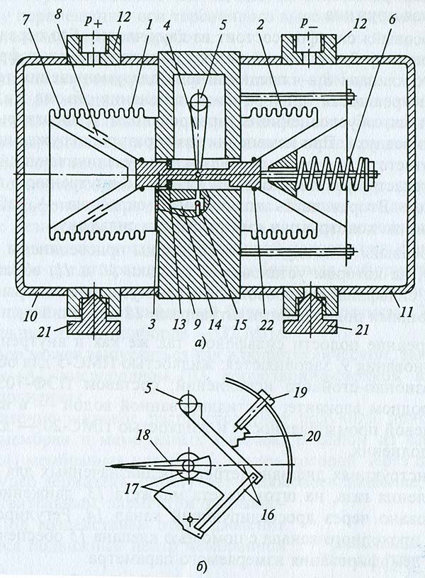
Рис. 2.23Дифференциальный сильфонный манометр:
а – схема привода стрелки;
б – блок первичного преобразования;
1 – «плюсовый» сильфон;
2 – «минусовый» сильфон;
3 – шток;
4 – рычаг;
5 – торсионный вывод;
6 – цилиндрическая пружина;
7 – компенсатор;
8 – плоскостный клапан;
9 – основание;
10 и 11 – крышки;
12 – подводящий штуцер;
13 – манжета;
14 – дросселирующий канал;
15 – клапан;
16 – рычажная система;
17 – трибко-секторный механизм;
18 – стрелка;
19 – регулировочный винт;
20 – натяжная пружина;
21 – пробка;
22 – уплотнительное резиновое кольцо«Плюсовый» 1 и «минусовый» 2 сильфоны (рис. Рис. 2.23, б) соединены между собой штоком 3, функционально связанным с рычагом 4, который, в свою очередь, неподвижно закреплен на оси торсионного вывода 5. К концу штока на выходе «минусового» сильфона присоединена цилиндрическая пружина 6, закрепленная нижним основанием на компенсаторе 7 и работающая на растяжение. Каждому номинальному перепаду давления соответствует определенная пружина.
«Плюсовый» сильфон состоит из двух частей. Его первая часть (компенсатор 7, состоящий из трех дополнительных гофр и плоскостных клапанов 8) предназначена для уменьшения температурной погрешности прибора из-за изменения объема жидкости-наполнителя, обусловленного варьированием температуры окружающего воздуха. При изменении температуры окружающей среды и соответственно рабочей жидкости ее увеличивающийся объем перетекает через плоскостный клапан во внутреннюю полость сильфонов. Вторая часть «плюсового» сильфона рабочая и идентична по конструкции «минусовому» сильфону.
«Плюсовый» и «минусовый» сильфоны присоединены к основанию 9, на котором установлены крышки 10 и 11, образующие вместе с сильфонами «плюсовую» и «минусовую» камеры с соответствующими подводящими штуцерами 12 давления р + и рВнутренние объемы сильфонов, так же как и внутренняя полость основания 9, заполняются: жидкостью ПМС-5 для обычного и коррозионно-стойкого исполнений; составом ПЭФ-703110 – в кислородном варианте; дистиллированной водой – в варианте для пищевой промышленности и жидкостью ПМС-20 – для газового исполнения.
В конструкциях дифманометров, предназначенных для измерения давления газа, на шток одета манжета 13, движение среды организовано через дросселирующий канал 14. Регулированием размера проходного канала с помощью клапана 15 обеспечивается степень демпфирования измеряемого параметра.
Дифманометр работает следующим образом. Среды «плюсового» и «минусового» давления поступают через подводящие штуцеры в «плюсовую» и «минусовую» камеры соответственно. «Плюсовое» давление в большей степени воздействует на сильфон 1, сжимая его. Это приводит к перетоку находящейся внутри жидкости в «минусовый» сильфон, который растягивается и разжимает цилиндрическую пружину. Такая динамика происходит до уравновешивания сил взаимодействия между «плюсовым» сильфоном и парой – «минусовый» сильфон – цилиндрическая пружина. Мерой деформации сильфонов и их упругого взаимодействия служит перемещение штока, которое передается на рычаг и соответственно на ось торсионного вывода. На этой оси (рис. 2.23,а) закреплена рычажная система 16, обеспечивающая передачу вращения оси торсионного вывода к трибко-секторному механизму 17 и стрелке 18. Таким образом, воздействие на один из сильфонов приводит к угловому перемещению оси торсионного вывода и затем к повороту указательной стрелки прибора.
Регулировочным винтом 19 с помощью натяжной пружины 20 производится корректировка нулевой точки прибора.
Пробки 21 предназначены для продувки импульсных линий, промывки измерительных полостей сильфонного блока, слива рабочей среды, заполнения измерительных полостей разделительной жидкостью при вводе прибора в работу.
При односторонней перегрузке одной из камер происходит сжатие сильфона и перемещение штока. Клапан в виде уплотнительного резинового кольца 22 садится в гнездо основания, перекрывает переток жидкости из внутренней полости сильфона, и таким образом предотвращается его необратимая деформация. При непродолжительных перегрузках разность «плюсового» и «минусового» давления на сильфонный блок может достигать 25 МПа, а в отдельных типах приборов не превышать 32 МПа.
прибор может выпускаться как в общетеническом, так и в аммиачном (А), кислородном (К), коррозионно-стойком-пищевом (Пп) исполнениях.
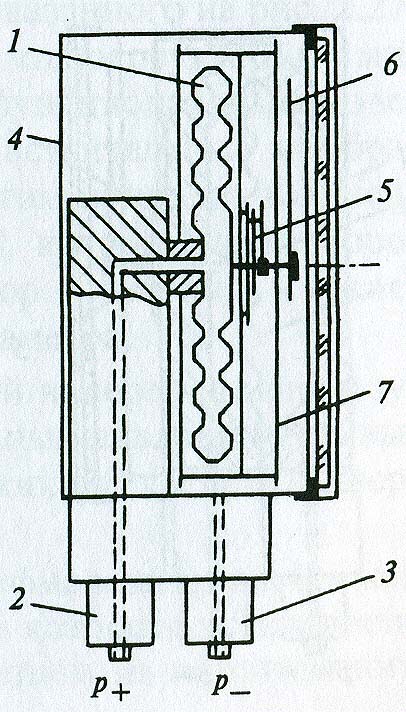
Рис. 2.24Показывающий дифференциальный манометр на основе мембранной коробки:
1 – мембранная коробка;
2 – держатель «плюсового» давления;
3 – держатель «минусового» давления;
4 – корпус;
5 – передаточный механизм;
6 – стрелка;
7 – циферблаДостаточно широкое распространение получили приборы на основе мембран и мембранных коробок. В одном из вариантов (рис. 2.24) мембранная коробка 1, внутрь которой через подводящий штуцер держателя 2 поступает «плюсовое» давление, является чувствительным элементом дифманометра. Под воздействием этого давления смещается подвижный центр мембранной коробки.
«Минусовое» давление через подводящий штуцер держателя 3 подается внутрь герметичного корпуса 4 прибора и воздействует на мембранную коробку снаружи, создавая противодействие перемещению ее подвижного центра. Таким образом «плюсовое» и «минусовое» давления уравновешивают друг друга, а перемещение подвижного центра мембранной коробки свидетельствует о величине разностного – дифференциального давления. Этот сдвиг через передаточный механизм передается на указательную стрелку 6, которая на шкале циферблата 7 показывает измеряемое дифференциальное давление.
Диапазон измеряемого давления определяется свойствами мембран и ограничивается, как правило, в пределах от 0 до 0,4…40 кПа. При этом класс точности может составлять 1,5; 1,0; 0,6; 0,4, а в некоторых приборах 0,25.
Обязательная конструктивная герметичность корпуса определяет высокую защищенность от внешних воздействий и определяется в основном уровнем IP66.
В качестве материала для чувствительных элементов приборов используется бериллиевая и другие бронзы, а также нержавеющая сталь, для штуцеров, передаточных механизмов – медные сплавы, коррозионно-стойкие сплавы, включая нержавеющую сталь.
Приборы могут изготавливаться в корпусах малых (63 мм), средних (100 мм), и больших (160 мм) диаметров.
Мембранные показывающие дифференциальные манометры, как и приборы с мембранными коробками, используются для измерения малых значений дифференциального давления. Отличительная особенность – устойчивая работа при высоком статическом давлении.
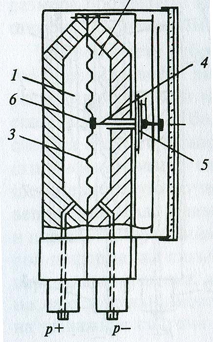
Рис. 2.25Мембранные показывающие дифференциальные манометры с вертикальной мембраной:
1 – «плюсовая» камера;
2 – «минусовая» камера;
3 – чувствительная гофрированная мембрана;
4 – передающий шток;
5 – передаточный механизм;
6 – предохранительный клапанДифманометр с вертикальной мембраной (Рис. 2.25) состоит из «плюсовой» 1 и «минусовой» 2 рабочих камер, разделенных чувствительной гофрированной мембраной 3. Под воздействием давления мембрана деформируется, в результате чего перемещается ее центр вместе с закрепленным на нем передающим штоком 4. Линейное смещение штока в передаточном механизме 5 преобразуется в осевое вращение трибки, и соответственно указательной стрелки, отсчитывающей на шкале прибора измеряемое давление.
Для сохранения работоспособности чувствительной гофрированной мембраны при превышении максимального допустимого статического давления предусмотрен открывающийся предохранительный клапан 6. Причем конструкции этих клапанов могут быть различны. Соответственно такие приборы не могут использоваться, когда не допускается контакт сред из «плюсовой» и «минусовой» камер.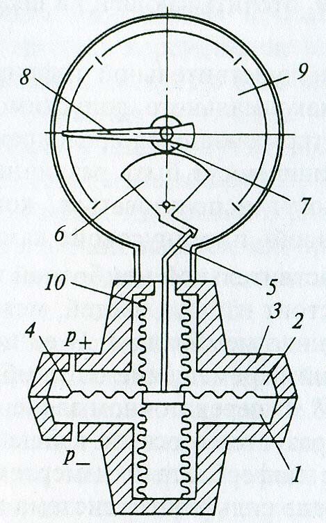
Рис. 2.26Мембранный показывающий дифференциальный манометр с горизонтальной мембраной:
1 – «плюсовая» камера;
2 – «минусовая» камера;
3 – входной блок;
4 - чувствительная гофрированная мембрана;
5 – толкатель;
6 – сектор;
7 – трибка;
8 – стрелка;
9 – циферблат;
10 – разделительный сильфонДифманометр с горизонтальной чувствительной мембраной показан на рис. 2.26. Входной блок 3 состоит из двух частей, между которыми устанавливается гофрированная мембрана 4. В ее центре закреплен толкатель 5, передающий перемещение от мембраны, через сектор 6, трибку 7 к стрелке 8. В этом передаточном звене линейное перемещение толкателя преобразуется в осевое вращение стрелки 8, отслеживающей на шкале циферблата 9 измеряемое давление. В этой конструкции применена сильфонная система вывода толкателя из зоны рабочего давления. Разделительный сильфон 10 своим основанием герметично закрепляется на центре чувствительной мембраны, а верхней частью также герметично прикрепляется к входному блоку. Такая конструкция исключает контакт измеряемой и окружающей сред.
Конструкция входного блока предусматривает возможность промывки или продувки «плюсовой» и «минусовой» камер и обеспечивает применение таких приборов для работы даже в условиях загрязненных рабочих сред.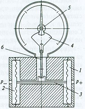
Рис. 2.27Мембранный двухкамерный показывающий дифманометр:
1 – «плюсовая» камера;
2 – «минусовая» камера;
3 – передающий шток;
4 – сектор;
5 – трибка;
6 – коромыслоДвухкамерная система измерения дифференциального давления применена в конструкции прибора, показанного на рис. 2.27. Измеряемые потоки среды направляются в «плюсовую» 1 и «минусовую» 2 рабочие камеры, основными функциональными элементами которых являются автономные чувствительные мембраны. Преобладание одного давления над другим приводит к линейному перемещению передающего штока 3, которое через коромысло 6 передается соответственно на сектор 4, трибку 5 и систему стрелочной индикации измеряемого параметра.
Дифманометры с двухкамерной системой измерения используются для измерения малых дифференциальных давлений при высоких статических нагрузках, вязких сред и сред с твердыми вкраплениями.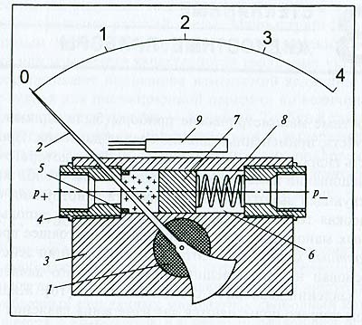
Рис. 2.28.Дифманометр с магнитным преобразователем:
1 – поворотный магнит;
2 – стрелка;
3 – корпус;
4 – магнитный поршень;
5 – фторопластовый сальник;
6 – рабочий канал;
7 – пробка;
8 – диапазонная пружина;
9 – блок электроконтактовПринципиально иной показывающий дифманометр изображен на рис. 2.28. Поворотный магнит 1, на торце которого установлена стрелка 2, размещен в корпусе 3, выполненном из немагнитного металла. Магнитный поршень, уплотненный фторопластовым сальником 5, может передвигаться в рабочем канале 6. Магнитный поршень 4 со стороны «минусового» давления подпирает пробка 7, в свою очередь поджимаемая диапазонной пружиной 8.
Среда «плюсового» давления через соответствующий подводящий штуцер воздействует на магнитный поршень и сдвигает его вместе с пробкой 7 по каналу 6 до уравновешивания такого смещения противодействующими силами – «минусовым» давлением и диапазонной пружиной. Движение магнитного поршня приводит к осевому вращению поворотного магнита и соответственно указательной стрелки. Такой сдвиг пропорционален перемещению стрелки. Полное согласование достигается подбором упругих характеристик диапазонной пружины.
В дифманометре с магнитным преобразователем предусмотрен блок 9, замыкающий и размыкающий соответствующие контакты при прохождении вблизи его магнитного поршня.
Приборы с магнитным преобразователем устойчивы к воздействию статического давления (до 10 МПа). Они обеспечивают относительно невысокую погрешность (примерно 2 %) в диапазоне функционирования до 0,4 Мпа и используются для измерения давления воздуха, газов, различных жидкостей.[ http://jumas.ru/index.php?area=1&p=static&page=razdel_2_3_2]
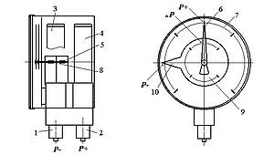
Показывающий дифференциальный манометр на основе трубчатой пружины1 и 2 – держатели;
3 и 4 – трубчатые пружины;
5 и 8 – трибки;
6 – стрелка «плюсового» давления;
7 и 9 – шкалы избыточного давления;
10 – стрелка «минусового» давленияВ приборах такого типа на автономных держателях 1 и 2, соединенных вместе, установлены трубчатые пружины. Каждый держатель вместе с трубчатым чувствительным элементом образовывают автономные измерительные каналы. Среда «плюсового» давления поступает через входной штуцер держателя 2 в трубку 4, деформирует ее овал, в результате чего перемещается наконечник трубки и это перемещение через соответствующий зубчатый сектор передается на трибку 5. Эта трибка соответственно приводит к отклонению указательной стрелки 6, которая показывает на шкале 7 значение «плюсового» избыточного давления.
«Минусовое» давление посредством держателя 1, трубчатой пружины 3, трибки 8 приводит к перемещению циферблата 9, объединенного со стрелкой 10, которая на шкале 7 отслеживает значение измеряемого параметра.Дифференциальные манометры (далее – дифманометры), как отмечалось в п.1.3, являются названием отнесенным в нашей стране к показывающим приборам. (Устройства, обеспечивающие электрический выходной сигнал, пропорциональный измеряемому дифференциальному давлению имеют название измерительных преобразователей разности давлений). Хотя отдельные производители, а также некоторые специалисты-эксплуатанционщики измерительные преобразователи разности давлений также называют дифманометрами.
Дифманометры нашли основное применение в технологических процессах для измерения, контроля, регистрации и регулирования следующих параметров:
· расхода различных жидких, газообразных и парообразных сред по перепаду давления на разного рода сужающих устройствах (стандартных диафрагмах, соплах, включая сопла Вентури) и дополнительно вводимых в поток гидро- и аэродинамических сопротивлениях, например на преобразователях типа Annubar или на нестандартных гидро- и аэродинамических препятствиях;
· перепада - разности давления, вакуумметрических, избыточных, в двух точках технологического цикла, включая потери на фильтрах систем вентиляции и кондиционирования воздуха;
· уровня жидких сред по величине гидростатического столба.
Согласно ГОСТ 18140–84/23/, предельные номинальные перепады давления дифманометров-расходомеров, верхние пределы или сумма абсолютных значений верхних пределов измерений дифманометров-перепадомеров должны приниматься из следующего ряда:
10; 16; 25; 40; 63; 100; 160; 250; 400; 630 Па;
1; 1,6; 2,5; 4; 6,3; 10; 16; 25; 40; 63; 100; 160; 250; 400; 630 кПа;
1; 1,6; 2,5; 4; 6,3 МПа.
У дифманометров-расходомеров верхние пределы измерений выбираются из ряда, определяемого выражением:
А = а × 10n, (2.7)
где а – одно из чисел следующего ряда: 1; 1,25; 1,6; 2,0; 2,5; 3,2; 4; 5; 6,3; 8; n – целое (положительное или отрицательное) число или нуль.
Верхние пределы измерений или сумма абсолютных значений верхних пределов измерений дифманометров-уровнемеров следует выбирать и ряда:
0,25; 0,4; 0,63; 1,0; 1,6; 2,5; 4,0; 6,3; 10; 16; 25; 40; 63; 100 и 160 метров.
Одной из важных характеристик дифманометров является предельно допустимое рабочее избыточное давление, т. е. избыточное давление, которое могут выдержать рабочие каналы без необратимой деформации чувствительных элементов. Такое значение параметра принимается из следующего ряда:
25; 40; 63; 100; 160; 250; 400 и 630 кПа;
1; 1,6; 2,5; 4; 6,3; 10; 16; 25; 32; 40 и 63 МПа.
Нижние пределы измерений дифманометров-расходо-меров из-за неустойчивости работы стандартных сужающих устройств при малых Числах Рейнольдса измеряемого потока не должны превышать 30 % шкалы прибора. У преобразователей Annubar этот предел не превышает 10 % при сохранении объявленного класса точности (1,0).
Классы точности дифманометров принимаются из ряда: 0,25; 0,5; 1,0; 1,5.
Дифманометры должны иметь линейную шкалу при измерении уровня или перепада, линейную или квадратичную – при измерении расхода.
Дифманометры могут иметь условные обозначения, предложенные в методике п.1.4. Указываются модель прибора, причем на первом месте в обозначении фиксируется измеряемый параметр – тип измерителя (дифманометр), затем – принцип измерения и функция, предельный номинальный перепад, избыточное рабочее давление, класс точности. Например, дифманометр сильфонный показывающий в корпусе диаметром 160 мм, на предельный номинальный перепад давления 630 кПа, с рабочим избыточным давлением 32 МПа, класса точности 1,5 обозначается как
ДСП 160 (0…630 кПа)-32 МПа-1,5.
После этого допускается указывать дополнительные обозначения, например исполнение по «IP», измеряемой среде, присоединительным линиям и т. д.
Специфика измерения дифференциального давления обусловливает наличие в дифманометрах устройств продувки импульсных линий без необходимости демонтажа прибора или его узлов.
При испытаниях, а также в нормальных условиях отечественные дифманометры, согласно требований производителя, должны обеспечивать заданные метрологические характеристики после выдержки не менее 6-ти часов при температуре окружающей среды:
20 ± 2 или 23 ± 2 оС – для приборов классов точности 0,5; 0,6 и 1;
20 ± 5 или 23 ± 5 оС – для приборов класса точности 1,5.
Современные конструкции из-за снижения металлоемкости и совершенствования преобразователей позволяют сокращать время температурной адаптации у некоторых моделей до нескольких десятков минут.
Конкретная температура приведена в ТУ на измеритель и должна регистрироваться в техническом описании или паспорте на прибор.
Дифманометры, не защищенные от одностороннего воздействия, должны выдерживать перегрузку со стороны среды «плюсового» давления, превышающую предельные номинальные перепады на 10…50 %. «Плюсовым», в противовес «минусовому», называют большее из двух давлений среды, поступающей на вход дифференциального манометра.
Конструкции, у которых предусмотрены односторонние перегрузки, должны выдерживать десятикратные, стократные или двухсот пятидесятикратные односторонние перегрузки/23/.
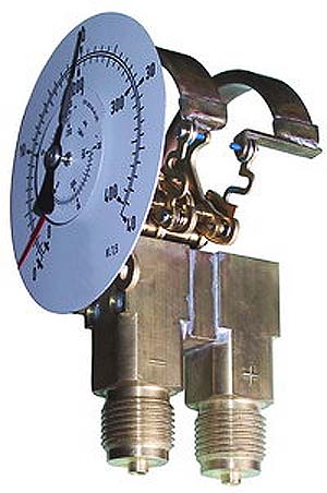
Показывающие дифференциальные манометры на основе трубчатой пружины находят широкое применение для визуализации расхода различных сред, гидродинамических потерь в системах теплового отопления.
Дифференциальное давление, т. е. разность давлений р отсчитывается стрелкой на шкале циферблата.
Дифманометры такого типа, исходя из особенностей трубчатых пружин, обеспечивают работоспособность в промышленных условиях в диапазоне от 0 до 100 МПа.[ http://jumas.ru/index.php?area=1&p=static&page=razdel2_2_4]
Тематики
Синонимы
EN
- differential gauge pressure
- differential manometer
- differential pressure gage
- differential pressure indicator
- differential-pressure gage
DE
FR
Англо-русский словарь нормативно-технической терминологии > differential pressure gage
-
13 differential-pressure gage
дифференциальный манометр
дифманометр
Манометр для измерения разности двух давлений.
Примечание
Дифманометр с верхним пределом измерения не более 40000 Па (4000 кгс/м2) называется микроманометром.
[ГОСТ 8.271-77]
дифференциальный манометр
-
[Лугинский Я. Н. и др. Англо-русский словарь по электротехнике и электроэнергетике. 2-е издание - М.: РУССО, 1995 - 616 с.]EN
differential-pressure gage
(engineering) Apparatus to measure pressure differences between two points in a system; it can be a pressured liquid column balanced by a pressured liquid reservoir, a formed metallic pressure element with opposing force, or an electrical-electronic gage (such as strain, thermal-conductivity, or ionization).
[ http://www.answers.com/topic/differential-pressure-gage#ixzz1gzzibWaQ]Малые значения дифференциального давления могут измеряться приборами на основе мембран и сильфонов.
Манометры дифференциальные сильфонные показывающие типа ДСП-160 нашли широкое применение на территории СНГ. Принцип их действия основан на деформации двух автономных сильфонных блоков, находящихся под воздействием «плюсового» и «минусового» давления. Эти деформации преобразовываются в перемещение указательной стрелки прибора. Перемещение стрелки осуществляется до установления равновесия между «плюсовым» сильфоном, с одной стороны, и «минусовым» и цилиндрической пружиной - с другой.
Рис. 2.23Дифференциальный сильфонный манометр:
а – схема привода стрелки;
б – блок первичного преобразования;
1 – «плюсовый» сильфон;
2 – «минусовый» сильфон;
3 – шток;
4 – рычаг;
5 – торсионный вывод;
6 – цилиндрическая пружина;
7 – компенсатор;
8 – плоскостный клапан;
9 – основание;
10 и 11 – крышки;
12 – подводящий штуцер;
13 – манжета;
14 – дросселирующий канал;
15 – клапан;
16 – рычажная система;
17 – трибко-секторный механизм;
18 – стрелка;
19 – регулировочный винт;
20 – натяжная пружина;
21 – пробка;
22 – уплотнительное резиновое кольцо«Плюсовый» 1 и «минусовый» 2 сильфоны (рис. Рис. 2.23, б) соединены между собой штоком 3, функционально связанным с рычагом 4, который, в свою очередь, неподвижно закреплен на оси торсионного вывода 5. К концу штока на выходе «минусового» сильфона присоединена цилиндрическая пружина 6, закрепленная нижним основанием на компенсаторе 7 и работающая на растяжение. Каждому номинальному перепаду давления соответствует определенная пружина.
«Плюсовый» сильфон состоит из двух частей. Его первая часть (компенсатор 7, состоящий из трех дополнительных гофр и плоскостных клапанов 8) предназначена для уменьшения температурной погрешности прибора из-за изменения объема жидкости-наполнителя, обусловленного варьированием температуры окружающего воздуха. При изменении температуры окружающей среды и соответственно рабочей жидкости ее увеличивающийся объем перетекает через плоскостный клапан во внутреннюю полость сильфонов. Вторая часть «плюсового» сильфона рабочая и идентична по конструкции «минусовому» сильфону.
«Плюсовый» и «минусовый» сильфоны присоединены к основанию 9, на котором установлены крышки 10 и 11, образующие вместе с сильфонами «плюсовую» и «минусовую» камеры с соответствующими подводящими штуцерами 12 давления р + и рВнутренние объемы сильфонов, так же как и внутренняя полость основания 9, заполняются: жидкостью ПМС-5 для обычного и коррозионно-стойкого исполнений; составом ПЭФ-703110 – в кислородном варианте; дистиллированной водой – в варианте для пищевой промышленности и жидкостью ПМС-20 – для газового исполнения.
В конструкциях дифманометров, предназначенных для измерения давления газа, на шток одета манжета 13, движение среды организовано через дросселирующий канал 14. Регулированием размера проходного канала с помощью клапана 15 обеспечивается степень демпфирования измеряемого параметра.
Дифманометр работает следующим образом. Среды «плюсового» и «минусового» давления поступают через подводящие штуцеры в «плюсовую» и «минусовую» камеры соответственно. «Плюсовое» давление в большей степени воздействует на сильфон 1, сжимая его. Это приводит к перетоку находящейся внутри жидкости в «минусовый» сильфон, который растягивается и разжимает цилиндрическую пружину. Такая динамика происходит до уравновешивания сил взаимодействия между «плюсовым» сильфоном и парой – «минусовый» сильфон – цилиндрическая пружина. Мерой деформации сильфонов и их упругого взаимодействия служит перемещение штока, которое передается на рычаг и соответственно на ось торсионного вывода. На этой оси (рис. 2.23,а) закреплена рычажная система 16, обеспечивающая передачу вращения оси торсионного вывода к трибко-секторному механизму 17 и стрелке 18. Таким образом, воздействие на один из сильфонов приводит к угловому перемещению оси торсионного вывода и затем к повороту указательной стрелки прибора.
Регулировочным винтом 19 с помощью натяжной пружины 20 производится корректировка нулевой точки прибора.
Пробки 21 предназначены для продувки импульсных линий, промывки измерительных полостей сильфонного блока, слива рабочей среды, заполнения измерительных полостей разделительной жидкостью при вводе прибора в работу.
При односторонней перегрузке одной из камер происходит сжатие сильфона и перемещение штока. Клапан в виде уплотнительного резинового кольца 22 садится в гнездо основания, перекрывает переток жидкости из внутренней полости сильфона, и таким образом предотвращается его необратимая деформация. При непродолжительных перегрузках разность «плюсового» и «минусового» давления на сильфонный блок может достигать 25 МПа, а в отдельных типах приборов не превышать 32 МПа.
прибор может выпускаться как в общетеническом, так и в аммиачном (А), кислородном (К), коррозионно-стойком-пищевом (Пп) исполнениях.
Рис. 2.24Показывающий дифференциальный манометр на основе мембранной коробки:
1 – мембранная коробка;
2 – держатель «плюсового» давления;
3 – держатель «минусового» давления;
4 – корпус;
5 – передаточный механизм;
6 – стрелка;
7 – циферблаДостаточно широкое распространение получили приборы на основе мембран и мембранных коробок. В одном из вариантов (рис. 2.24) мембранная коробка 1, внутрь которой через подводящий штуцер держателя 2 поступает «плюсовое» давление, является чувствительным элементом дифманометра. Под воздействием этого давления смещается подвижный центр мембранной коробки.
«Минусовое» давление через подводящий штуцер держателя 3 подается внутрь герметичного корпуса 4 прибора и воздействует на мембранную коробку снаружи, создавая противодействие перемещению ее подвижного центра. Таким образом «плюсовое» и «минусовое» давления уравновешивают друг друга, а перемещение подвижного центра мембранной коробки свидетельствует о величине разностного – дифференциального давления. Этот сдвиг через передаточный механизм передается на указательную стрелку 6, которая на шкале циферблата 7 показывает измеряемое дифференциальное давление.
Диапазон измеряемого давления определяется свойствами мембран и ограничивается, как правило, в пределах от 0 до 0,4…40 кПа. При этом класс точности может составлять 1,5; 1,0; 0,6; 0,4, а в некоторых приборах 0,25.
Обязательная конструктивная герметичность корпуса определяет высокую защищенность от внешних воздействий и определяется в основном уровнем IP66.
В качестве материала для чувствительных элементов приборов используется бериллиевая и другие бронзы, а также нержавеющая сталь, для штуцеров, передаточных механизмов – медные сплавы, коррозионно-стойкие сплавы, включая нержавеющую сталь.
Приборы могут изготавливаться в корпусах малых (63 мм), средних (100 мм), и больших (160 мм) диаметров.
Мембранные показывающие дифференциальные манометры, как и приборы с мембранными коробками, используются для измерения малых значений дифференциального давления. Отличительная особенность – устойчивая работа при высоком статическом давлении.
Рис. 2.25Мембранные показывающие дифференциальные манометры с вертикальной мембраной:
1 – «плюсовая» камера;
2 – «минусовая» камера;
3 – чувствительная гофрированная мембрана;
4 – передающий шток;
5 – передаточный механизм;
6 – предохранительный клапанДифманометр с вертикальной мембраной (Рис. 2.25) состоит из «плюсовой» 1 и «минусовой» 2 рабочих камер, разделенных чувствительной гофрированной мембраной 3. Под воздействием давления мембрана деформируется, в результате чего перемещается ее центр вместе с закрепленным на нем передающим штоком 4. Линейное смещение штока в передаточном механизме 5 преобразуется в осевое вращение трибки, и соответственно указательной стрелки, отсчитывающей на шкале прибора измеряемое давление.
Для сохранения работоспособности чувствительной гофрированной мембраны при превышении максимального допустимого статического давления предусмотрен открывающийся предохранительный клапан 6. Причем конструкции этих клапанов могут быть различны. Соответственно такие приборы не могут использоваться, когда не допускается контакт сред из «плюсовой» и «минусовой» камер.
Рис. 2.26Мембранный показывающий дифференциальный манометр с горизонтальной мембраной:
1 – «плюсовая» камера;
2 – «минусовая» камера;
3 – входной блок;
4 - чувствительная гофрированная мембрана;
5 – толкатель;
6 – сектор;
7 – трибка;
8 – стрелка;
9 – циферблат;
10 – разделительный сильфонДифманометр с горизонтальной чувствительной мембраной показан на рис. 2.26. Входной блок 3 состоит из двух частей, между которыми устанавливается гофрированная мембрана 4. В ее центре закреплен толкатель 5, передающий перемещение от мембраны, через сектор 6, трибку 7 к стрелке 8. В этом передаточном звене линейное перемещение толкателя преобразуется в осевое вращение стрелки 8, отслеживающей на шкале циферблата 9 измеряемое давление. В этой конструкции применена сильфонная система вывода толкателя из зоны рабочего давления. Разделительный сильфон 10 своим основанием герметично закрепляется на центре чувствительной мембраны, а верхней частью также герметично прикрепляется к входному блоку. Такая конструкция исключает контакт измеряемой и окружающей сред.
Конструкция входного блока предусматривает возможность промывки или продувки «плюсовой» и «минусовой» камер и обеспечивает применение таких приборов для работы даже в условиях загрязненных рабочих сред.
Рис. 2.27Мембранный двухкамерный показывающий дифманометр:
1 – «плюсовая» камера;
2 – «минусовая» камера;
3 – передающий шток;
4 – сектор;
5 – трибка;
6 – коромыслоДвухкамерная система измерения дифференциального давления применена в конструкции прибора, показанного на рис. 2.27. Измеряемые потоки среды направляются в «плюсовую» 1 и «минусовую» 2 рабочие камеры, основными функциональными элементами которых являются автономные чувствительные мембраны. Преобладание одного давления над другим приводит к линейному перемещению передающего штока 3, которое через коромысло 6 передается соответственно на сектор 4, трибку 5 и систему стрелочной индикации измеряемого параметра.
Дифманометры с двухкамерной системой измерения используются для измерения малых дифференциальных давлений при высоких статических нагрузках, вязких сред и сред с твердыми вкраплениями.
Рис. 2.28.Дифманометр с магнитным преобразователем:
1 – поворотный магнит;
2 – стрелка;
3 – корпус;
4 – магнитный поршень;
5 – фторопластовый сальник;
6 – рабочий канал;
7 – пробка;
8 – диапазонная пружина;
9 – блок электроконтактовПринципиально иной показывающий дифманометр изображен на рис. 2.28. Поворотный магнит 1, на торце которого установлена стрелка 2, размещен в корпусе 3, выполненном из немагнитного металла. Магнитный поршень, уплотненный фторопластовым сальником 5, может передвигаться в рабочем канале 6. Магнитный поршень 4 со стороны «минусового» давления подпирает пробка 7, в свою очередь поджимаемая диапазонной пружиной 8.
Среда «плюсового» давления через соответствующий подводящий штуцер воздействует на магнитный поршень и сдвигает его вместе с пробкой 7 по каналу 6 до уравновешивания такого смещения противодействующими силами – «минусовым» давлением и диапазонной пружиной. Движение магнитного поршня приводит к осевому вращению поворотного магнита и соответственно указательной стрелки. Такой сдвиг пропорционален перемещению стрелки. Полное согласование достигается подбором упругих характеристик диапазонной пружины.
В дифманометре с магнитным преобразователем предусмотрен блок 9, замыкающий и размыкающий соответствующие контакты при прохождении вблизи его магнитного поршня.
Приборы с магнитным преобразователем устойчивы к воздействию статического давления (до 10 МПа). Они обеспечивают относительно невысокую погрешность (примерно 2 %) в диапазоне функционирования до 0,4 Мпа и используются для измерения давления воздуха, газов, различных жидкостей.[ http://jumas.ru/index.php?area=1&p=static&page=razdel_2_3_2]
Показывающий дифференциальный манометр на основе трубчатой пружины1 и 2 – держатели;
3 и 4 – трубчатые пружины;
5 и 8 – трибки;
6 – стрелка «плюсового» давления;
7 и 9 – шкалы избыточного давления;
10 – стрелка «минусового» давленияВ приборах такого типа на автономных держателях 1 и 2, соединенных вместе, установлены трубчатые пружины. Каждый держатель вместе с трубчатым чувствительным элементом образовывают автономные измерительные каналы. Среда «плюсового» давления поступает через входной штуцер держателя 2 в трубку 4, деформирует ее овал, в результате чего перемещается наконечник трубки и это перемещение через соответствующий зубчатый сектор передается на трибку 5. Эта трибка соответственно приводит к отклонению указательной стрелки 6, которая показывает на шкале 7 значение «плюсового» избыточного давления.
«Минусовое» давление посредством держателя 1, трубчатой пружины 3, трибки 8 приводит к перемещению циферблата 9, объединенного со стрелкой 10, которая на шкале 7 отслеживает значение измеряемого параметра.Дифференциальные манометры (далее – дифманометры), как отмечалось в п.1.3, являются названием отнесенным в нашей стране к показывающим приборам. (Устройства, обеспечивающие электрический выходной сигнал, пропорциональный измеряемому дифференциальному давлению имеют название измерительных преобразователей разности давлений). Хотя отдельные производители, а также некоторые специалисты-эксплуатанционщики измерительные преобразователи разности давлений также называют дифманометрами.
Дифманометры нашли основное применение в технологических процессах для измерения, контроля, регистрации и регулирования следующих параметров:
· расхода различных жидких, газообразных и парообразных сред по перепаду давления на разного рода сужающих устройствах (стандартных диафрагмах, соплах, включая сопла Вентури) и дополнительно вводимых в поток гидро- и аэродинамических сопротивлениях, например на преобразователях типа Annubar или на нестандартных гидро- и аэродинамических препятствиях;
· перепада - разности давления, вакуумметрических, избыточных, в двух точках технологического цикла, включая потери на фильтрах систем вентиляции и кондиционирования воздуха;
· уровня жидких сред по величине гидростатического столба.
Согласно ГОСТ 18140–84/23/, предельные номинальные перепады давления дифманометров-расходомеров, верхние пределы или сумма абсолютных значений верхних пределов измерений дифманометров-перепадомеров должны приниматься из следующего ряда:
10; 16; 25; 40; 63; 100; 160; 250; 400; 630 Па;
1; 1,6; 2,5; 4; 6,3; 10; 16; 25; 40; 63; 100; 160; 250; 400; 630 кПа;
1; 1,6; 2,5; 4; 6,3 МПа.
У дифманометров-расходомеров верхние пределы измерений выбираются из ряда, определяемого выражением:
А = а × 10n, (2.7)
где а – одно из чисел следующего ряда: 1; 1,25; 1,6; 2,0; 2,5; 3,2; 4; 5; 6,3; 8; n – целое (положительное или отрицательное) число или нуль.
Верхние пределы измерений или сумма абсолютных значений верхних пределов измерений дифманометров-уровнемеров следует выбирать и ряда:
0,25; 0,4; 0,63; 1,0; 1,6; 2,5; 4,0; 6,3; 10; 16; 25; 40; 63; 100 и 160 метров.
Одной из важных характеристик дифманометров является предельно допустимое рабочее избыточное давление, т. е. избыточное давление, которое могут выдержать рабочие каналы без необратимой деформации чувствительных элементов. Такое значение параметра принимается из следующего ряда:
25; 40; 63; 100; 160; 250; 400 и 630 кПа;
1; 1,6; 2,5; 4; 6,3; 10; 16; 25; 32; 40 и 63 МПа.
Нижние пределы измерений дифманометров-расходо-меров из-за неустойчивости работы стандартных сужающих устройств при малых Числах Рейнольдса измеряемого потока не должны превышать 30 % шкалы прибора. У преобразователей Annubar этот предел не превышает 10 % при сохранении объявленного класса точности (1,0).
Классы точности дифманометров принимаются из ряда: 0,25; 0,5; 1,0; 1,5.
Дифманометры должны иметь линейную шкалу при измерении уровня или перепада, линейную или квадратичную – при измерении расхода.
Дифманометры могут иметь условные обозначения, предложенные в методике п.1.4. Указываются модель прибора, причем на первом месте в обозначении фиксируется измеряемый параметр – тип измерителя (дифманометр), затем – принцип измерения и функция, предельный номинальный перепад, избыточное рабочее давление, класс точности. Например, дифманометр сильфонный показывающий в корпусе диаметром 160 мм, на предельный номинальный перепад давления 630 кПа, с рабочим избыточным давлением 32 МПа, класса точности 1,5 обозначается как
ДСП 160 (0…630 кПа)-32 МПа-1,5.
После этого допускается указывать дополнительные обозначения, например исполнение по «IP», измеряемой среде, присоединительным линиям и т. д.
Специфика измерения дифференциального давления обусловливает наличие в дифманометрах устройств продувки импульсных линий без необходимости демонтажа прибора или его узлов.
При испытаниях, а также в нормальных условиях отечественные дифманометры, согласно требований производителя, должны обеспечивать заданные метрологические характеристики после выдержки не менее 6-ти часов при температуре окружающей среды:
20 ± 2 или 23 ± 2 оС – для приборов классов точности 0,5; 0,6 и 1;
20 ± 5 или 23 ± 5 оС – для приборов класса точности 1,5.
Современные конструкции из-за снижения металлоемкости и совершенствования преобразователей позволяют сокращать время температурной адаптации у некоторых моделей до нескольких десятков минут.
Конкретная температура приведена в ТУ на измеритель и должна регистрироваться в техническом описании или паспорте на прибор.
Дифманометры, не защищенные от одностороннего воздействия, должны выдерживать перегрузку со стороны среды «плюсового» давления, превышающую предельные номинальные перепады на 10…50 %. «Плюсовым», в противовес «минусовому», называют большее из двух давлений среды, поступающей на вход дифференциального манометра.
Конструкции, у которых предусмотрены односторонние перегрузки, должны выдерживать десятикратные, стократные или двухсот пятидесятикратные односторонние перегрузки/23/.
Показывающие дифференциальные манометры на основе трубчатой пружины находят широкое применение для визуализации расхода различных сред, гидродинамических потерь в системах теплового отопления.
Дифференциальное давление, т. е. разность давлений р отсчитывается стрелкой на шкале циферблата.
Дифманометры такого типа, исходя из особенностей трубчатых пружин, обеспечивают работоспособность в промышленных условиях в диапазоне от 0 до 100 МПа.[ http://jumas.ru/index.php?area=1&p=static&page=razdel2_2_4]
Тематики
Синонимы
EN
- differential gauge pressure
- differential manometer
- differential pressure gage
- differential pressure indicator
- differential-pressure gage
DE
FR
Англо-русский словарь нормативно-технической терминологии > differential-pressure gage
-
14 American Wire Gauge System
американский сортамент проводов
Американская система классификации кабелей, в которой чем больше условный номер изделия, тем меньше диаметр проводника. В телекоммуникационных сетях, как правило, используются провода калибров 22AWG, 24AWG и 26AWG (табл. А-4).
[Л.М. Невдяев. Телекоммуникационные технологии. Англо-русский толковый словарь-справочник. Под редакцией Ю.М. Горностаева. Москва, 2002]
калибр проводника AWG
-
[Интент]Калибр провода
AWG и МСМСечение, мм2
Число проводов х диаметр 1го провода в мм
38
0,009
7х0, 040
36
0,014
7х0, 051
34
0,022
7х0, 064
32
0,034/ 0,035
7х0,080/ 19х0,051
30
0,057/ 0,059
7х0,102/ 19х0,064
28
0,089/ 0,09
7х0,127/ 19х0,080
26
0,141/ 0,155
7х0,160/ 19х0,102
24
0,227/ 0,241
7х0,203/ 19х0,127
22
0,355/ 0,382/ 0,5
7х0,254/ 19х0,160/ 16х0,2
20
0,563/ 0,616/ 0,75
7х0,320/ 19х0,203/ 24х0,2
18
0,897/ 0,963/ 1
7х0,404/ 19х0,254/ 32х0,20
16
1,229/ 1,5
19х0,287/ 30х0,25
14
1,941/ 2,5
19х0,361/ 50х0,25
12
3,085/ 4
19х0,455/ 56х0,30
10
5,26/ 6
19х0,60/ 84х0,30
8
8,35/ 10
19х0,75/ 80х0,40
6
13,29/ 16
19х0,96/ 128х0,4
4
21,14/ 25
19х1,19/ 200х0,40
2
33,61/ 35
19х1,50/ 280х0,40
1
42,38/ 50
19х1,686/ 400х0,40
1/0
53,47
19х1,89
2/0
67,4
19х2,126
2/0
70
356х0,50
3/0
95
727х0,39
4/0
107,17
19х2,68
37х2,09
37х2,29
177,3
37х2,47
202,7
37х2,64
253,4
37х2,95
61х2,52
61х2,62
354,7
61х2,72
31х2,82
405,4
61х2,91
61х3,09
506,7
61х3,25
В этой системе меньшему числовому значению соответствует более толстый провод. Такое «перевёрнутое» обозначение диаметра сложилось исторически: проволоку изготавливают волочением, и номер (калибр) обозначает количество последовательных протягиваний через всё уменьшающиеся отверстия в волоке до получения нужного диаметра. Так, для получения проволоки AWG 24 диаметром около 0,5 мм заготовка AWG 0 диаметром свыше 8 мм протягивалась 24 раза. В калибрах AWG довольно часто обозначают не только размеры (диаметр, сечение) проводов, но и размеры прутков, стержней, трубок.
[Википедия]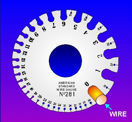
Американский стандарт на калибры проводов (American Wire Gauge)
Одножильные нелуженые медные провода Обозначение в стандарте AWG Номинальный диаметр Площадь сечения
мм X ммПогонный вес Погонное сопротивление мм дюймы грамм на метр фунтов на 1000 футов Ом на метр Ом на 1000 футов 10
2.600
0.1024
5.309
46.77
31.43
0.0033
0.999
11
2.300
0.0906
4.155
37.09
24.92
0.0041
1.260
12
2.050
0.0807
3.301
29.42
19.77
0.0052
1.588
13
1.830
0.0720
2.630
23.33
15.68
0.0066
2.003
14
1.630
0.0642
2.087
18.50
12.43
0.0083
2.525
15
1.450
0.0571
1.651
14.67
9.858
0.0104
3.184
16
1.290
0.0508
1.307
11.63
7.818
0.0132
4.016
17
1.150
0.0453
1.039
9.23
6.200
0.0166
5.064
18
1.020
0.0402
0.817
7.32
4.917
0.0209
6.385
19
0.912
0.0359
0.653
5.80
3.899
0.026
8.051
20
0.813
0.0320
0.519
4.60
3.092
0.033
10.15
21
0.724
0.0285
0.412
3.65
2.452
0.042
12.80
22
0.643
0.0253
0.325
2.89
1.945
0.053
16.14
23
0.574
0.0226
0.259
2.29
1.542
0.067
20.36
24
0.511
0.0201
0.205
1.82
1.223
0.084
25.67
25
0.455
0.0179
0.163
1.44
0.9699
0.106
32.37
26
0.404
0.0159
0.128
1.14
0.7692
0.134
40.81
27
0.361
0.0142
0.102
0.908
0.6100
0.169
51.47
28
0.320
0.0126
0.080
0.720
0.4837
0.213
64.90
29
0.287
0.0113
0.065
0.571
0.3836
0.268
81.83
30
0.254
0.0100
0.051
0.453
0.3042
0.339
103.2
31
0.226
0.0089
0.040
0.359
0.2413
0.427
130.1
32
0.203
0.0080
0.032
0.285
0.1913
0.538
164.1
33
0.180
0.0071
0.025
0.226
0.1517
0.679
206.9
34
0.160
0.0063
0.020
0.179
0.1203
0.856
260.9
35
0.142
0.0056
0.016
0.142
0.09542
1.086
331.0
36
0.127
0.0050
0.013
0.113
0.07568
1.361
414.8
37
0.114
0.0045
0.010
0.091
0.06130
1.680
512.1
38
0.102
0.0040
0.008
0.071
0.04759
2.128
648.6
39
0.089
0.0035
0.006
0.056
0.03774
2.781
847.8
40
0.079
0.0031
0.005
0.045
0.02993
3.543
1080.0
Обозначение в стандарте AWG мм дюймы Площадь сечения
мм X ммграмм на метр фунтов на 1000 футов Ом на метр Ом на 1000 футов Номинальный диаметр Погонный вес Погонное сопротивление Многожильные луженые медные провода
Обозн.
в стандарте AWGКоличество жил/толщина одной в AWG Приведенный диаметр Площадь сечения
мм X ммМинимальный вес Погонное сопротивление мм дюймы грамм на метр фунтов на 1000 футов Ом на метр Ом на 1000 футов 36
7/44
0.153
0.0060
0.014
0.11
0.076
1.3609
141.80
34
7/42
0.191
0.0075
0.022
0.18
0.121
0.8560
260.90
32
7/40
0.203
0.0080
0.034
0.29
0.195
0.5384
164.10
32
19/44
0.229
0.0090
0.039
0.29
0.195
0.5384
164.10
30
7/38
0.305
0.0120
0.056
0.45
0.304
0.3674
112.00
30
19/42
0.305
0.0120
0.060
0.45
0.304
0.3674
112.00
28
7/36
0.381
0.0150
0.071
0.72
0.484
0.2320
70.70
28
19/40
0.406
0.0160
0.093
0.72
0.484
0.2320
70.70
27
7/35
0.457
0.0180
0.111
0.91
0.614
0.1824
55.60
26
7/34
0.483
0.0190
0.140
1.15
0.770
0.146
44.40
26
10/36
0.553
0.0218
0.127
1.15
0.770
0.146
44.40
26
19/38
0.508
0.0200
0.153
1.15
0.770
0.146
44.40
24
7/32
0.610
0.0240
0.226
1.83
1.229
0.091
27.70
24
10/34
0.584
0.0230
0.200
1.83
1.229
0.091
27.70
24
19/36
0.610
0.0240
0.239
1.83
1.229
0.091
27.70
24
42/40
0.584
0.0230
0.201
1.83
1.229
0.091
27.70
22
72/30
0.762
0.0300
0.352
2.90
1.947
0.057
17.50
22
19/34
0.787
0.0310
0.380
2.90
1.947
0.057
17.50
22
26/36
0.762
0.0300
0.327
2.90
1.947
0.057
17.50
20
7/28
0.890
0.0350
0.504
4.62
3.103
0.036
10.90
20
10/30
0.890
0.0350
0.504
4.62
3.103
0.036
10.90
20
19/32
0.940
0.0370
0.612
4.62
3.103
0.036
10.90
20
26/34
0.914
0.0360
0.520
4.62
3.103
0.036
10.90
20
42/36
0.914
0.0360
0.533
4.62
3.103
0.036
10.90
18
7/26
1.220
0.0480
0.891
7.34
4.93
0.023
6.92
18
16/30
1.200
0.0472
0.808
7.34
4.93
0.023
6.92
18
19/30
1.240
0.0488
0.957
7.34
4.93
0.023
6.92
18
42/34
1.200
0.0472
0.819
7.34
4.93
0.023
6.92
18
65/36
1.200
0.0472
0.845
7.34
4.93
0.023
6.92
16
7/24
1.520
0.0598
1.420
11.68
7.85
0.014
4.35
16
19/29
1.470
0.0579
1.216
11.68
7.85
0.014
4.35
16
26/30
1.500
0.0591
1.310
11.68
7.85
0.014
4.35
16
65/34
1.500
0.0591
1.300
11.68
7.85
0.014
4.35
16
105/36
1.500
0.0591
1.365
11.68
7.85
0.014
4.35
14
7/22
1.850
0.0728
2.260
18.60
12.5
0.009
2.73
14
19/26
1.850
0.0728
1.930
18.60
12.5
0.009
2.73
14
42/30
1.850
0.0728
2.060
18.60
12.5
0.009
2.73
14
105/34
1.850
0.0728
2.100
18.60
12.5
0.009
2.73
12
7/20
2.440
0.0961
3.610
29.56
19.9
0.0056
1.71
12
19/25
2.360
0.0929
3.070
29.56
19.9
0.0056
1.71
12
65/30
2.410
0.0949
3.270
29.56
19.9
0.0056
1.71
12
165/34
2.410
0.0949
3.300
47.00
31.6
0.0056
1.71
10
37/26
2.920
0.1150
4.710
47.00
31.6
0.0035
1.08
10
65/28
2.950
0.1161
5.230
47.00
31.6
0.0035
1.08
10
105/30
2.950
0.1161
5.355
47.00
31.6
0.0035
1.08
8
49/25
3.734
0.1470
8.007
70.73
47.5
0.0022
0.67
8
133/29
3.734
0.1470
8.662
76.52
51.4
0.0020
0.61
8
655/36
3.734
0.1470
8.479
73.78
49.6
0.0020
0.62
6
133/27
4.674
0.1840
13.675
120.75
81.1
0.0015
0.47
6
259/30
4.674
0.1840
13.209
116.60
78.4
0.0013
0.40
6
1050/36
4.674
0.1840
13.388
118.26
79.5
0.0013
0.39
4
133/25
5.898
0.2322
21.733
191.99
129.0
0.0008
0.24
4
259/26
5.898
0.2322
26.629
235.16
158.0
0.0007
0.20
4
1666/36
5.898
0.2322
21.242
187.66
126.1
0.0008
0.25
2
1333/23
7.417
0.2920
34.648
306.00
205.6
0.00049
0.15
2
259/26
7.417
0.2920
33.392
294.87
198.1
0.00052
0.16
2
665/30
7.417
0.2920
33.915
229.36
201.2
0.00052
0.16
2
2646/36
7.417
0.2920
33.737
298.05
200.3
0.00052
0.16
1
163.195.0
8.331
0.3280
43.418
383.35
257.6
0.00039
0.12
1
172.508.0
8.331
0.3280
42.322
373.83
251.2
0.00043
0.13
1
817/30
8.331
0.3280
41.667
367.73
247.1
0.00043
0.13
1
2109/34
8.331
0.3280
42.690
376.94
253.3
0.00039
0.12
1/0
133/21
9.347
0.3680
55.098
486.71
327.1
0.00031
0.10
1/0
259/24
9.347
0.3680
53.364
471.39
316.8
0.00032
0.10
2/0
133/20
10.516
0.4140
69.458
613.38
412.2
0.00025
0.08
2/0
259/23
10.516
0.4140
67.472
595.88
400.4
0.00025
0.08
3/0
259/22
11.786
0.4640
83.230
746.62
501.7
0.00020
0.06
3/0
427/24
11.786
0.4640
87.979
777.12
522.2
0.00019
0.06
4/0
259/21
13.259
0.5220
107.297
950.76
638.9
0.00016
0.05
4/0
427/23
13.259
0.5220
111.237
982.21
660.0
0.00015
0.05
Обозн.
в стандарте AWGКоличество жил/толщина одной в AWG мм дюймы Площадь сечения
мм X ммграмм на метр фунтов на 1000 футов Ом на метр Ом на 1000 футов Приведенный диаметр Минимальный вес Погонное сопротивление Тематики
- кабели, провода...
Синонимы
EN
Англо-русский словарь нормативно-технической терминологии > American Wire Gauge System
15 B and S gage
американский сортамент проводов
Американская система классификации кабелей, в которой чем больше условный номер изделия, тем меньше диаметр проводника. В телекоммуникационных сетях, как правило, используются провода калибров 22AWG, 24AWG и 26AWG (табл. А-4).
[Л.М. Невдяев. Телекоммуникационные технологии. Англо-русский толковый словарь-справочник. Под редакцией Ю.М. Горностаева. Москва, 2002]
калибр проводника AWG
-
[Интент]Калибр провода
AWG и МСМСечение, мм2
Число проводов х диаметр 1го провода в мм
38
0,009
7х0, 040
36
0,014
7х0, 051
34
0,022
7х0, 064
32
0,034/ 0,035
7х0,080/ 19х0,051
30
0,057/ 0,059
7х0,102/ 19х0,064
28
0,089/ 0,09
7х0,127/ 19х0,080
26
0,141/ 0,155
7х0,160/ 19х0,102
24
0,227/ 0,241
7х0,203/ 19х0,127
22
0,355/ 0,382/ 0,5
7х0,254/ 19х0,160/ 16х0,2
20
0,563/ 0,616/ 0,75
7х0,320/ 19х0,203/ 24х0,2
18
0,897/ 0,963/ 1
7х0,404/ 19х0,254/ 32х0,20
16
1,229/ 1,5
19х0,287/ 30х0,25
14
1,941/ 2,5
19х0,361/ 50х0,25
12
3,085/ 4
19х0,455/ 56х0,30
10
5,26/ 6
19х0,60/ 84х0,30
8
8,35/ 10
19х0,75/ 80х0,40
6
13,29/ 16
19х0,96/ 128х0,4
4
21,14/ 25
19х1,19/ 200х0,40
2
33,61/ 35
19х1,50/ 280х0,40
1
42,38/ 50
19х1,686/ 400х0,40
1/0
53,47
19х1,89
2/0
67,4
19х2,126
2/0
70
356х0,50
3/0
95
727х0,39
4/0
107,17
19х2,68
37х2,09
37х2,29
177,3
37х2,47
202,7
37х2,64
253,4
37х2,95
61х2,52
61х2,62
354,7
61х2,72
31х2,82
405,4
61х2,91
61х3,09
506,7
61х3,25
В этой системе меньшему числовому значению соответствует более толстый провод. Такое «перевёрнутое» обозначение диаметра сложилось исторически: проволоку изготавливают волочением, и номер (калибр) обозначает количество последовательных протягиваний через всё уменьшающиеся отверстия в волоке до получения нужного диаметра. Так, для получения проволоки AWG 24 диаметром около 0,5 мм заготовка AWG 0 диаметром свыше 8 мм протягивалась 24 раза. В калибрах AWG довольно часто обозначают не только размеры (диаметр, сечение) проводов, но и размеры прутков, стержней, трубок.
[Википедия]Американский стандарт на калибры проводов (American Wire Gauge)
Одножильные нелуженые медные провода Обозначение в стандарте AWG Номинальный диаметр Площадь сечения
мм X ммПогонный вес Погонное сопротивление мм дюймы грамм на метр фунтов на 1000 футов Ом на метр Ом на 1000 футов 10
2.600
0.1024
5.309
46.77
31.43
0.0033
0.999
11
2.300
0.0906
4.155
37.09
24.92
0.0041
1.260
12
2.050
0.0807
3.301
29.42
19.77
0.0052
1.588
13
1.830
0.0720
2.630
23.33
15.68
0.0066
2.003
14
1.630
0.0642
2.087
18.50
12.43
0.0083
2.525
15
1.450
0.0571
1.651
14.67
9.858
0.0104
3.184
16
1.290
0.0508
1.307
11.63
7.818
0.0132
4.016
17
1.150
0.0453
1.039
9.23
6.200
0.0166
5.064
18
1.020
0.0402
0.817
7.32
4.917
0.0209
6.385
19
0.912
0.0359
0.653
5.80
3.899
0.026
8.051
20
0.813
0.0320
0.519
4.60
3.092
0.033
10.15
21
0.724
0.0285
0.412
3.65
2.452
0.042
12.80
22
0.643
0.0253
0.325
2.89
1.945
0.053
16.14
23
0.574
0.0226
0.259
2.29
1.542
0.067
20.36
24
0.511
0.0201
0.205
1.82
1.223
0.084
25.67
25
0.455
0.0179
0.163
1.44
0.9699
0.106
32.37
26
0.404
0.0159
0.128
1.14
0.7692
0.134
40.81
27
0.361
0.0142
0.102
0.908
0.6100
0.169
51.47
28
0.320
0.0126
0.080
0.720
0.4837
0.213
64.90
29
0.287
0.0113
0.065
0.571
0.3836
0.268
81.83
30
0.254
0.0100
0.051
0.453
0.3042
0.339
103.2
31
0.226
0.0089
0.040
0.359
0.2413
0.427
130.1
32
0.203
0.0080
0.032
0.285
0.1913
0.538
164.1
33
0.180
0.0071
0.025
0.226
0.1517
0.679
206.9
34
0.160
0.0063
0.020
0.179
0.1203
0.856
260.9
35
0.142
0.0056
0.016
0.142
0.09542
1.086
331.0
36
0.127
0.0050
0.013
0.113
0.07568
1.361
414.8
37
0.114
0.0045
0.010
0.091
0.06130
1.680
512.1
38
0.102
0.0040
0.008
0.071
0.04759
2.128
648.6
39
0.089
0.0035
0.006
0.056
0.03774
2.781
847.8
40
0.079
0.0031
0.005
0.045
0.02993
3.543
1080.0
Обозначение в стандарте AWG мм дюймы Площадь сечения
мм X ммграмм на метр фунтов на 1000 футов Ом на метр Ом на 1000 футов Номинальный диаметр Погонный вес Погонное сопротивление Многожильные луженые медные провода
Обозн.
в стандарте AWGКоличество жил/толщина одной в AWG Приведенный диаметр Площадь сечения
мм X ммМинимальный вес Погонное сопротивление мм дюймы грамм на метр фунтов на 1000 футов Ом на метр Ом на 1000 футов 36
7/44
0.153
0.0060
0.014
0.11
0.076
1.3609
141.80
34
7/42
0.191
0.0075
0.022
0.18
0.121
0.8560
260.90
32
7/40
0.203
0.0080
0.034
0.29
0.195
0.5384
164.10
32
19/44
0.229
0.0090
0.039
0.29
0.195
0.5384
164.10
30
7/38
0.305
0.0120
0.056
0.45
0.304
0.3674
112.00
30
19/42
0.305
0.0120
0.060
0.45
0.304
0.3674
112.00
28
7/36
0.381
0.0150
0.071
0.72
0.484
0.2320
70.70
28
19/40
0.406
0.0160
0.093
0.72
0.484
0.2320
70.70
27
7/35
0.457
0.0180
0.111
0.91
0.614
0.1824
55.60
26
7/34
0.483
0.0190
0.140
1.15
0.770
0.146
44.40
26
10/36
0.553
0.0218
0.127
1.15
0.770
0.146
44.40
26
19/38
0.508
0.0200
0.153
1.15
0.770
0.146
44.40
24
7/32
0.610
0.0240
0.226
1.83
1.229
0.091
27.70
24
10/34
0.584
0.0230
0.200
1.83
1.229
0.091
27.70
24
19/36
0.610
0.0240
0.239
1.83
1.229
0.091
27.70
24
42/40
0.584
0.0230
0.201
1.83
1.229
0.091
27.70
22
72/30
0.762
0.0300
0.352
2.90
1.947
0.057
17.50
22
19/34
0.787
0.0310
0.380
2.90
1.947
0.057
17.50
22
26/36
0.762
0.0300
0.327
2.90
1.947
0.057
17.50
20
7/28
0.890
0.0350
0.504
4.62
3.103
0.036
10.90
20
10/30
0.890
0.0350
0.504
4.62
3.103
0.036
10.90
20
19/32
0.940
0.0370
0.612
4.62
3.103
0.036
10.90
20
26/34
0.914
0.0360
0.520
4.62
3.103
0.036
10.90
20
42/36
0.914
0.0360
0.533
4.62
3.103
0.036
10.90
18
7/26
1.220
0.0480
0.891
7.34
4.93
0.023
6.92
18
16/30
1.200
0.0472
0.808
7.34
4.93
0.023
6.92
18
19/30
1.240
0.0488
0.957
7.34
4.93
0.023
6.92
18
42/34
1.200
0.0472
0.819
7.34
4.93
0.023
6.92
18
65/36
1.200
0.0472
0.845
7.34
4.93
0.023
6.92
16
7/24
1.520
0.0598
1.420
11.68
7.85
0.014
4.35
16
19/29
1.470
0.0579
1.216
11.68
7.85
0.014
4.35
16
26/30
1.500
0.0591
1.310
11.68
7.85
0.014
4.35
16
65/34
1.500
0.0591
1.300
11.68
7.85
0.014
4.35
16
105/36
1.500
0.0591
1.365
11.68
7.85
0.014
4.35
14
7/22
1.850
0.0728
2.260
18.60
12.5
0.009
2.73
14
19/26
1.850
0.0728
1.930
18.60
12.5
0.009
2.73
14
42/30
1.850
0.0728
2.060
18.60
12.5
0.009
2.73
14
105/34
1.850
0.0728
2.100
18.60
12.5
0.009
2.73
12
7/20
2.440
0.0961
3.610
29.56
19.9
0.0056
1.71
12
19/25
2.360
0.0929
3.070
29.56
19.9
0.0056
1.71
12
65/30
2.410
0.0949
3.270
29.56
19.9
0.0056
1.71
12
165/34
2.410
0.0949
3.300
47.00
31.6
0.0056
1.71
10
37/26
2.920
0.1150
4.710
47.00
31.6
0.0035
1.08
10
65/28
2.950
0.1161
5.230
47.00
31.6
0.0035
1.08
10
105/30
2.950
0.1161
5.355
47.00
31.6
0.0035
1.08
8
49/25
3.734
0.1470
8.007
70.73
47.5
0.0022
0.67
8
133/29
3.734
0.1470
8.662
76.52
51.4
0.0020
0.61
8
655/36
3.734
0.1470
8.479
73.78
49.6
0.0020
0.62
6
133/27
4.674
0.1840
13.675
120.75
81.1
0.0015
0.47
6
259/30
4.674
0.1840
13.209
116.60
78.4
0.0013
0.40
6
1050/36
4.674
0.1840
13.388
118.26
79.5
0.0013
0.39
4
133/25
5.898
0.2322
21.733
191.99
129.0
0.0008
0.24
4
259/26
5.898
0.2322
26.629
235.16
158.0
0.0007
0.20
4
1666/36
5.898
0.2322
21.242
187.66
126.1
0.0008
0.25
2
1333/23
7.417
0.2920
34.648
306.00
205.6
0.00049
0.15
2
259/26
7.417
0.2920
33.392
294.87
198.1
0.00052
0.16
2
665/30
7.417
0.2920
33.915
229.36
201.2
0.00052
0.16
2
2646/36
7.417
0.2920
33.737
298.05
200.3
0.00052
0.16
1
163.195.0
8.331
0.3280
43.418
383.35
257.6
0.00039
0.12
1
172.508.0
8.331
0.3280
42.322
373.83
251.2
0.00043
0.13
1
817/30
8.331
0.3280
41.667
367.73
247.1
0.00043
0.13
1
2109/34
8.331
0.3280
42.690
376.94
253.3
0.00039
0.12
1/0
133/21
9.347
0.3680
55.098
486.71
327.1
0.00031
0.10
1/0
259/24
9.347
0.3680
53.364
471.39
316.8
0.00032
0.10
2/0
133/20
10.516
0.4140
69.458
613.38
412.2
0.00025
0.08
2/0
259/23
10.516
0.4140
67.472
595.88
400.4
0.00025
0.08
3/0
259/22
11.786
0.4640
83.230
746.62
501.7
0.00020
0.06
3/0
427/24
11.786
0.4640
87.979
777.12
522.2
0.00019
0.06
4/0
259/21
13.259
0.5220
107.297
950.76
638.9
0.00016
0.05
4/0
427/23
13.259
0.5220
111.237
982.21
660.0
0.00015
0.05
Обозн.
в стандарте AWGКоличество жил/толщина одной в AWG мм дюймы Площадь сечения
мм X ммграмм на метр фунтов на 1000 футов Ом на метр Ом на 1000 футов Приведенный диаметр Минимальный вес Погонное сопротивление Тематики
- кабели, провода...
Синонимы
EN
Англо-русский словарь нормативно-технической терминологии > B and S gage
16 Brown and Sharp gage
американский сортамент проводов
Американская система классификации кабелей, в которой чем больше условный номер изделия, тем меньше диаметр проводника. В телекоммуникационных сетях, как правило, используются провода калибров 22AWG, 24AWG и 26AWG (табл. А-4).
[Л.М. Невдяев. Телекоммуникационные технологии. Англо-русский толковый словарь-справочник. Под редакцией Ю.М. Горностаева. Москва, 2002]
калибр проводника AWG
-
[Интент]Калибр провода
AWG и МСМСечение, мм2
Число проводов х диаметр 1го провода в мм
38
0,009
7х0, 040
36
0,014
7х0, 051
34
0,022
7х0, 064
32
0,034/ 0,035
7х0,080/ 19х0,051
30
0,057/ 0,059
7х0,102/ 19х0,064
28
0,089/ 0,09
7х0,127/ 19х0,080
26
0,141/ 0,155
7х0,160/ 19х0,102
24
0,227/ 0,241
7х0,203/ 19х0,127
22
0,355/ 0,382/ 0,5
7х0,254/ 19х0,160/ 16х0,2
20
0,563/ 0,616/ 0,75
7х0,320/ 19х0,203/ 24х0,2
18
0,897/ 0,963/ 1
7х0,404/ 19х0,254/ 32х0,20
16
1,229/ 1,5
19х0,287/ 30х0,25
14
1,941/ 2,5
19х0,361/ 50х0,25
12
3,085/ 4
19х0,455/ 56х0,30
10
5,26/ 6
19х0,60/ 84х0,30
8
8,35/ 10
19х0,75/ 80х0,40
6
13,29/ 16
19х0,96/ 128х0,4
4
21,14/ 25
19х1,19/ 200х0,40
2
33,61/ 35
19х1,50/ 280х0,40
1
42,38/ 50
19х1,686/ 400х0,40
1/0
53,47
19х1,89
2/0
67,4
19х2,126
2/0
70
356х0,50
3/0
95
727х0,39
4/0
107,17
19х2,68
37х2,09
37х2,29
177,3
37х2,47
202,7
37х2,64
253,4
37х2,95
61х2,52
61х2,62
354,7
61х2,72
31х2,82
405,4
61х2,91
61х3,09
506,7
61х3,25
В этой системе меньшему числовому значению соответствует более толстый провод. Такое «перевёрнутое» обозначение диаметра сложилось исторически: проволоку изготавливают волочением, и номер (калибр) обозначает количество последовательных протягиваний через всё уменьшающиеся отверстия в волоке до получения нужного диаметра. Так, для получения проволоки AWG 24 диаметром около 0,5 мм заготовка AWG 0 диаметром свыше 8 мм протягивалась 24 раза. В калибрах AWG довольно часто обозначают не только размеры (диаметр, сечение) проводов, но и размеры прутков, стержней, трубок.
[Википедия]Американский стандарт на калибры проводов (American Wire Gauge)
Одножильные нелуженые медные провода Обозначение в стандарте AWG Номинальный диаметр Площадь сечения
мм X ммПогонный вес Погонное сопротивление мм дюймы грамм на метр фунтов на 1000 футов Ом на метр Ом на 1000 футов 10
2.600
0.1024
5.309
46.77
31.43
0.0033
0.999
11
2.300
0.0906
4.155
37.09
24.92
0.0041
1.260
12
2.050
0.0807
3.301
29.42
19.77
0.0052
1.588
13
1.830
0.0720
2.630
23.33
15.68
0.0066
2.003
14
1.630
0.0642
2.087
18.50
12.43
0.0083
2.525
15
1.450
0.0571
1.651
14.67
9.858
0.0104
3.184
16
1.290
0.0508
1.307
11.63
7.818
0.0132
4.016
17
1.150
0.0453
1.039
9.23
6.200
0.0166
5.064
18
1.020
0.0402
0.817
7.32
4.917
0.0209
6.385
19
0.912
0.0359
0.653
5.80
3.899
0.026
8.051
20
0.813
0.0320
0.519
4.60
3.092
0.033
10.15
21
0.724
0.0285
0.412
3.65
2.452
0.042
12.80
22
0.643
0.0253
0.325
2.89
1.945
0.053
16.14
23
0.574
0.0226
0.259
2.29
1.542
0.067
20.36
24
0.511
0.0201
0.205
1.82
1.223
0.084
25.67
25
0.455
0.0179
0.163
1.44
0.9699
0.106
32.37
26
0.404
0.0159
0.128
1.14
0.7692
0.134
40.81
27
0.361
0.0142
0.102
0.908
0.6100
0.169
51.47
28
0.320
0.0126
0.080
0.720
0.4837
0.213
64.90
29
0.287
0.0113
0.065
0.571
0.3836
0.268
81.83
30
0.254
0.0100
0.051
0.453
0.3042
0.339
103.2
31
0.226
0.0089
0.040
0.359
0.2413
0.427
130.1
32
0.203
0.0080
0.032
0.285
0.1913
0.538
164.1
33
0.180
0.0071
0.025
0.226
0.1517
0.679
206.9
34
0.160
0.0063
0.020
0.179
0.1203
0.856
260.9
35
0.142
0.0056
0.016
0.142
0.09542
1.086
331.0
36
0.127
0.0050
0.013
0.113
0.07568
1.361
414.8
37
0.114
0.0045
0.010
0.091
0.06130
1.680
512.1
38
0.102
0.0040
0.008
0.071
0.04759
2.128
648.6
39
0.089
0.0035
0.006
0.056
0.03774
2.781
847.8
40
0.079
0.0031
0.005
0.045
0.02993
3.543
1080.0
Обозначение в стандарте AWG мм дюймы Площадь сечения
мм X ммграмм на метр фунтов на 1000 футов Ом на метр Ом на 1000 футов Номинальный диаметр Погонный вес Погонное сопротивление Многожильные луженые медные провода
Обозн.
в стандарте AWGКоличество жил/толщина одной в AWG Приведенный диаметр Площадь сечения
мм X ммМинимальный вес Погонное сопротивление мм дюймы грамм на метр фунтов на 1000 футов Ом на метр Ом на 1000 футов 36
7/44
0.153
0.0060
0.014
0.11
0.076
1.3609
141.80
34
7/42
0.191
0.0075
0.022
0.18
0.121
0.8560
260.90
32
7/40
0.203
0.0080
0.034
0.29
0.195
0.5384
164.10
32
19/44
0.229
0.0090
0.039
0.29
0.195
0.5384
164.10
30
7/38
0.305
0.0120
0.056
0.45
0.304
0.3674
112.00
30
19/42
0.305
0.0120
0.060
0.45
0.304
0.3674
112.00
28
7/36
0.381
0.0150
0.071
0.72
0.484
0.2320
70.70
28
19/40
0.406
0.0160
0.093
0.72
0.484
0.2320
70.70
27
7/35
0.457
0.0180
0.111
0.91
0.614
0.1824
55.60
26
7/34
0.483
0.0190
0.140
1.15
0.770
0.146
44.40
26
10/36
0.553
0.0218
0.127
1.15
0.770
0.146
44.40
26
19/38
0.508
0.0200
0.153
1.15
0.770
0.146
44.40
24
7/32
0.610
0.0240
0.226
1.83
1.229
0.091
27.70
24
10/34
0.584
0.0230
0.200
1.83
1.229
0.091
27.70
24
19/36
0.610
0.0240
0.239
1.83
1.229
0.091
27.70
24
42/40
0.584
0.0230
0.201
1.83
1.229
0.091
27.70
22
72/30
0.762
0.0300
0.352
2.90
1.947
0.057
17.50
22
19/34
0.787
0.0310
0.380
2.90
1.947
0.057
17.50
22
26/36
0.762
0.0300
0.327
2.90
1.947
0.057
17.50
20
7/28
0.890
0.0350
0.504
4.62
3.103
0.036
10.90
20
10/30
0.890
0.0350
0.504
4.62
3.103
0.036
10.90
20
19/32
0.940
0.0370
0.612
4.62
3.103
0.036
10.90
20
26/34
0.914
0.0360
0.520
4.62
3.103
0.036
10.90
20
42/36
0.914
0.0360
0.533
4.62
3.103
0.036
10.90
18
7/26
1.220
0.0480
0.891
7.34
4.93
0.023
6.92
18
16/30
1.200
0.0472
0.808
7.34
4.93
0.023
6.92
18
19/30
1.240
0.0488
0.957
7.34
4.93
0.023
6.92
18
42/34
1.200
0.0472
0.819
7.34
4.93
0.023
6.92
18
65/36
1.200
0.0472
0.845
7.34
4.93
0.023
6.92
16
7/24
1.520
0.0598
1.420
11.68
7.85
0.014
4.35
16
19/29
1.470
0.0579
1.216
11.68
7.85
0.014
4.35
16
26/30
1.500
0.0591
1.310
11.68
7.85
0.014
4.35
16
65/34
1.500
0.0591
1.300
11.68
7.85
0.014
4.35
16
105/36
1.500
0.0591
1.365
11.68
7.85
0.014
4.35
14
7/22
1.850
0.0728
2.260
18.60
12.5
0.009
2.73
14
19/26
1.850
0.0728
1.930
18.60
12.5
0.009
2.73
14
42/30
1.850
0.0728
2.060
18.60
12.5
0.009
2.73
14
105/34
1.850
0.0728
2.100
18.60
12.5
0.009
2.73
12
7/20
2.440
0.0961
3.610
29.56
19.9
0.0056
1.71
12
19/25
2.360
0.0929
3.070
29.56
19.9
0.0056
1.71
12
65/30
2.410
0.0949
3.270
29.56
19.9
0.0056
1.71
12
165/34
2.410
0.0949
3.300
47.00
31.6
0.0056
1.71
10
37/26
2.920
0.1150
4.710
47.00
31.6
0.0035
1.08
10
65/28
2.950
0.1161
5.230
47.00
31.6
0.0035
1.08
10
105/30
2.950
0.1161
5.355
47.00
31.6
0.0035
1.08
8
49/25
3.734
0.1470
8.007
70.73
47.5
0.0022
0.67
8
133/29
3.734
0.1470
8.662
76.52
51.4
0.0020
0.61
8
655/36
3.734
0.1470
8.479
73.78
49.6
0.0020
0.62
6
133/27
4.674
0.1840
13.675
120.75
81.1
0.0015
0.47
6
259/30
4.674
0.1840
13.209
116.60
78.4
0.0013
0.40
6
1050/36
4.674
0.1840
13.388
118.26
79.5
0.0013
0.39
4
133/25
5.898
0.2322
21.733
191.99
129.0
0.0008
0.24
4
259/26
5.898
0.2322
26.629
235.16
158.0
0.0007
0.20
4
1666/36
5.898
0.2322
21.242
187.66
126.1
0.0008
0.25
2
1333/23
7.417
0.2920
34.648
306.00
205.6
0.00049
0.15
2
259/26
7.417
0.2920
33.392
294.87
198.1
0.00052
0.16
2
665/30
7.417
0.2920
33.915
229.36
201.2
0.00052
0.16
2
2646/36
7.417
0.2920
33.737
298.05
200.3
0.00052
0.16
1
163.195.0
8.331
0.3280
43.418
383.35
257.6
0.00039
0.12
1
172.508.0
8.331
0.3280
42.322
373.83
251.2
0.00043
0.13
1
817/30
8.331
0.3280
41.667
367.73
247.1
0.00043
0.13
1
2109/34
8.331
0.3280
42.690
376.94
253.3
0.00039
0.12
1/0
133/21
9.347
0.3680
55.098
486.71
327.1
0.00031
0.10
1/0
259/24
9.347
0.3680
53.364
471.39
316.8
0.00032
0.10
2/0
133/20
10.516
0.4140
69.458
613.38
412.2
0.00025
0.08
2/0
259/23
10.516
0.4140
67.472
595.88
400.4
0.00025
0.08
3/0
259/22
11.786
0.4640
83.230
746.62
501.7
0.00020
0.06
3/0
427/24
11.786
0.4640
87.979
777.12
522.2
0.00019
0.06
4/0
259/21
13.259
0.5220
107.297
950.76
638.9
0.00016
0.05
4/0
427/23
13.259
0.5220
111.237
982.21
660.0
0.00015
0.05
Обозн.
в стандарте AWGКоличество жил/толщина одной в AWG мм дюймы Площадь сечения
мм X ммграмм на метр фунтов на 1000 футов Ом на метр Ом на 1000 футов Приведенный диаметр Минимальный вес Погонное сопротивление Тематики
- кабели, провода...
Синонимы
EN
Англо-русский словарь нормативно-технической терминологии > Brown and Sharp gage
17 narrow gage lighting system
Большой англо-русский и русско-английский словарь > narrow gage lighting system
18 narrow gage lighting system
система светомаркировки ВПП с близким расположением огнейАнгло-русский словарь технических терминов > narrow gage lighting system
19 contact-system gage
Техника: габаритная ширина контактной сети20 narrow gage lighting system
Универсальный англо-русский словарь > narrow gage lighting system
СтраницыСм. также в других словарях:
System Rush — is a futuristic racing game for the Nokia N Gage platform. It was released in 2005 and available Worldwide through leading retailers.Infobox VG title = System Rush developer = Ideaworks 3D publisher = Nokia released = 2005 genre = racing game… … Wikipedia
system — 1 System, scheme, network, complex, organism, economy can mean an organized integrated whole made up of diverse but interrelated and interdependent parts. System usually implies that the component units of an aggregate exist and operate in unison … New Dictionary of Synonyms
Gage County, Nebraska — Infobox U.S. County county = Gage County state = Nebraska founded = 1855 seat wl = Beatrice largest city wl = Beatrice area total sq mi =860 area land sq mi =855 area water sq mi =5 area percentage = 0.54% census yr = 2000 pop = 22993 density km2 … Wikipedia
Gage Group Buildings — Infobox nrhp | name =Gage Group Ascher, Keith, and Gage Buildings nrhp type = caption =Gage Group Buildings (left to right: 30, 24, and 18 S. Michigan Avenue); the rightmost s façade is by Louis Sullivan. location= Chicago, Illinois lat degrees … Wikipedia
Gage R&R — Als Messsystemanalyse bzw. Messmittel Fähigkeitsananlyse oder Prüfmittel Fähigkeitsananlyse, kurz MSA (Englisch: Measurement System Analysis), bezeichnet man die Analyse der Fähigkeit von Messmitteln und kompletten Messsystemen in… … Deutsch Wikipedia
N-Gage — This article is about the mobile phone. For the 2008–2010 Nokia service, see N Gage (service). For the model railway N gauge, see N scale. Nokia N Gage Manufacturer Nokia Generation sixth generation … Wikipedia
N-Gage (service) — N Gage 2 and second generation N Gage redirects here, for the redesign of the N Gage console, see N Gage QD. The new N Gage logo … Wikipedia
N-Gage QD — Nokia N Gage QD Manufacturer Nokia Generation sixth generation era (1st gen N Gage) Retail availability May 2004 … Wikipedia
Cadillac Gage Commando — Infobox Weapon name=LAV 100, LAV 150 Commando (Armoured Fighting Vehicle) caption=Cadillac Gage XM706E2 origin=United States of America type=Light Armoured Vehicle is ranged= is bladed= is explosive= is artillery= is vehicle=yes is missile= is UK … Wikipedia
National Register of Historic Places listings in Gage County, Nebraska — Location of Gage County in Nebraska This is a list of the National Register of Historic Places listings in Gage County, Nebraska. This is intended to be a complete list of the properties and districts on the National Register of Historic Places… … Wikipedia
Matilda Joslyn Gage — Matilda Electa Joslyn Gage (Cicero, New York, March 24, 1826 – March 18, 1898 in Chicago) was a suffragist, a Native American activist, an abolitionist, a freethinker, and a prolific author, who was born with a hatred of oppression … Wikipedia
 18+© Академик, 2000-2024
- Обратная связь: Техподдержка, Реклама на сайте
Экспорт словарей на сайты, сделанные на PHP, Joomla, Drupal, WordPress, MODx.
Перевод: с английского на русский
с русского на английский- С русского на:
- Английский
- С английского на:
- Все языки
- Испанский
- Русский